
Hi,Master:
Platform: nrf52840
Bluetooth protocol stack: s140
When using qspi to communicate with external flash (communication speed 32M), occasional qspi communication exceptions occur in the product, or when a hand touches the IO1 pin, this phenomenon will recur. nrfx_qspi_cinstr_xfer will return NRFX_ERROR_TIMEOUT (13).
static  void _xfer_cinstr(uint8_t opcode, uint8_t *p_send_data, uint8_t send_data_len, uint8_t *p_rcv_data)
{
    uint32_t err_code;

    nrf_qspi_cinstr_conf_t cinstr_cfg = {
        .opcode    = opcode,
        .length    = send_data_len + 1,
        .io2_level = true,
        .io3_level = true,
        .wipwait   = true,
        .wren      = false
    };

    err_code = nrfx_qspi_cinstr_xfer(&cinstr_cfg, p_send_data, p_rcv_data);
    DEBUG_INFO("_xfer_cinstr = %d",err_code);
}
Some contexts and questions:
bool p25q_init(void)
{
    nrfx_qspi_config_t config = NRFX_QSPI_DEFAULT_CONFIG;

    config.pins.csn_pin = FLASH_CS_PIN;
    config.pins.sck_pin = FLASH_SCK_PIN;
    config.pins.io0_pin = FLASH_QSPI_IO0;
    config.pins.io1_pin = FLASH_QSPI_IO1;
    config.pins.io2_pin = FLASH_QSPI_IO2;
    config.pins.io3_pin = FLASH_QSPI_IO3;
    config.prot_if.readoc = NRF_QSPI_READOC_READ4O;
    config.prot_if.writeoc = NRF_QSPI_WRITEOC_PP4O;


    m_spi_is_init = true;
    err_code = nrfx_qspi_init(&config, NULL, NULL);
    ...
}

void p25q_uninit(void)
{

    if(m_spi_is_init == true)
	{
		p25q_power_down();
		nrfx_qspi_uninit();
		m_spi_is_init = false;
        NRFX_IRQ_PENDING_CLEAR(QSPI_IRQn);
	}

    //nrf_gpio_cfg_default(FLASH_CS_PIN);
    nrf_gpio_cfg_output(FLASH_CS_PIN);
    nrf_gpio_pin_set(FLASH_CS_PIN);
    nrf_gpio_cfg_default(FLASH_SCK_PIN);
    nrf_gpio_cfg_default(FLASH_QSPI_IO0);
    nrf_gpio_cfg_default(FLASH_QSPI_IO1);
    nrf_gpio_cfg_default(FLASH_QSPI_IO2);
    nrf_gpio_cfg_default(FLASH_QSPI_IO3);
}

void p25q_buffer_read(...)
{
	p25q_init();
    // read
    p25q_uninit();
}

void p25q_buffer_write(...)
{
	p25q_init();
    // write
    p25q_uninit();
}

void p25q_erase(...)
{
	p25q_init();
    // erase
    p25q_uninit();
}
problem:
1. Do I need to initialize these IO pins individually in p25q_init (void)? Each time a function is called, such as p25q_buffer_read, p25q_uninit () will be executed to reset all pins except csn to:
PIN_CNF
DIR: 0-input
INPUT:1-disconnect input buffer
PULL:0-Disabled = No Pull
DRIVE:0-S0S1
SENSE:0-Disabled
The nrfx_qspi_init in p25q_init does not initialize these external pins.
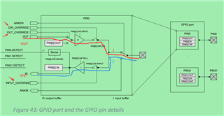
2.According to the reference manual 6.9.1 (shown below):
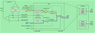
If the qspi data of MCU is written to the pin through red line 1, and read the data to the qspi peripheral via blue line 2,
p25q_uninit has configured the pins to the above state:
a).IINPUT: 1-disconnect input buffer has been disconnected here, and line 2 has been disconnected. How can I reach the qspi peripheral? Is the peripheral automatically controlling INPUT_OVERRIDE?
b).DIR: 0-input is set here as input, line 1 has been disconnected, how can the qspi peripheral data reach the pin, is the peripheral automatically controlling DIR_OVERRIDE?
How does this happen internally?
3.When I add the following code to p25q_init
 nrf_gpio_cfg(
        FLASH_QSPI_IO1,
        NRF_GPIO_PIN_DIR_INPUT,
        NRF_GPIO_PIN_INPUT_CONNECT,
        NRF_GPIO_PIN_PULLDOWN,//
        NRF_GPIO_PIN_H0H1,
        NRF_GPIO_PIN_NOSENSE);
Qspi communication abnormality no longer appears. This may have some connection with question 1?Or I don't add the above code, and add a 33pf capacitor to this pin to GNDCan also solve the problem. So I think this may be related to the IO port being configured as floating?
4.I want to know the internal input pull-up resistor value?
thank you very much.


 ?
?