Hey guys (and merry Christmas),
I'm working with a Laird BL652-DVK (nrF 52832 - chip), Nordic SDK v.14.2.0 and SES (Segger Embedded Studio v.4.30). I try to receive data from an accelerometer using spi. At first I configured the uart example because I want to send the data to my pc with uart and Termite v3.4. That's working.
Now I have implented the spi example into the uart example. I have configured spi and the accelerometer. After that I read the WHO_AM_I register (uint8_t read_data_1), but I get a wrong value. I get the value "11" instead of "33".... My code is below. If I read the "uint8_t read_data[1]" (commented out), I get the value "0x0". I really don't know, what to do. I hope someone can help me.
My code:
/**
* Copyright (c) 2014 - 2017, Nordic Semiconductor ASA
*
* All rights reserved.
*
* Redistribution and use in source and binary forms, with or without modification,
* are permitted provided that the following conditions are met:
*
* 1. Redistributions of source code must retain the above copyright notice, this
* list of conditions and the following disclaimer.
*
* 2. Redistributions in binary form, except as embedded into a Nordic
* Semiconductor ASA integrated circuit in a product or a software update for
* such product, must reproduce the above copyright notice, this list of
* conditions and the following disclaimer in the documentation and/or other
* materials provided with the distribution.
*
* 3. Neither the name of Nordic Semiconductor ASA nor the names of its
* contributors may be used to endorse or promote products derived from this
* software without specific prior written permission.
*
* 4. This software, with or without modification, must only be used with a
* Nordic Semiconductor ASA integrated circuit.
*
* 5. Any software provided in binary form under this license must not be reverse
* engineered, decompiled, modified and/or disassembled.
*
* THIS SOFTWARE IS PROVIDED BY NORDIC SEMICONDUCTOR ASA "AS IS" AND ANY EXPRESS
* OR IMPLIED WARRANTIES, INCLUDING, BUT NOT LIMITED TO, THE IMPLIED WARRANTIES
* OF MERCHANTABILITY, NONINFRINGEMENT, AND FITNESS FOR A PARTICULAR PURPOSE ARE
* DISCLAIMED. IN NO EVENT SHALL NORDIC SEMICONDUCTOR ASA OR CONTRIBUTORS BE
* LIABLE FOR ANY DIRECT, INDIRECT, INCIDENTAL, SPECIAL, EXEMPLARY, OR
* CONSEQUENTIAL DAMAGES (INCLUDING, BUT NOT LIMITED TO, PROCUREMENT OF SUBSTITUTE
* GOODS OR SERVICES; LOSS OF USE, DATA, OR PROFITS; OR BUSINESS INTERRUPTION)
* HOWEVER CAUSED AND ON ANY THEORY OF LIABILITY, WHETHER IN CONTRACT, STRICT
* LIABILITY, OR TORT (INCLUDING NEGLIGENCE OR OTHERWISE) ARISING IN ANY WAY OUT
* OF THE USE OF THIS SOFTWARE, EVEN IF ADVISED OF THE POSSIBILITY OF SUCH DAMAGE.
*
*/
/** @file
* @defgroup uart_example_main main.c
* @{
* @ingroup uart_example
* @brief UART Example Application main file.
*
* This file contains the source code for a sample application using UART.
*
*/
#include <stdbool.h>
#include <stdint.h>
#include <stdio.h>
#include <math.h>
#include "app_uart.h"
#include "app_error.h"
#include "nrf_delay.h"
#include "nrf.h"
#include "bsp.h"
#if defined (UART_PRESENT)
#include "nrf_uart.h"
#endif
#if defined (UARTE_PRESENT)
#include "nrf_uarte.h"
#endif
//spi header
#include <nrf_drv_spi.h>
#include "app_util_platform.h"
#include "nrf_gpio.h"
#include "boards.h"
#include <string.h>
#include "nrf_log.h"
#include "nrf_log_ctrl.h"
#include "nrf_log_default_backends.h"
#define MAX_TEST_DATA_BYTES (15U) /**< max number of test bytes to be used for tx and rx. */
#define UART_TX_BUF_SIZE 256 /**< UART TX buffer size. */
#define UART_RX_BUF_SIZE 256 /**< UART RX buffer size. */
#define UART_HWFC APP_UART_FLOW_CONTROL_DISABLED /* When UART is used for communication with the host do not use flow control.*/
//spi variables
#define SPI_INSTANCE 0 /**< SPI instance index. */
static const nrf_drv_spi_t spi = NRF_DRV_SPI_INSTANCE(SPI_INSTANCE); /**< SPI instance. */
static volatile bool spi_xfer_done; /**< Flag used to indicate that SPI instance completed the transfer. */
//uint8_t read_data[1];
uint8_t read_data[1];
//accel input register
uint8_t LIS3DH_CTRL_REG1[] = {0x20, 0x47}; //all axes, normal, 50Hz
uint8_t LIS3DH_CTRL_REG2[] = {0x21, 0x00}; //no highpass filter
uint8_t LIS3DH_CTRL_REG3[] = {0x22, 0x00}; //no interrupts
uint8_t LIS3DH_CTRL_REG4[] = {0x23, 0x88}; //all defaults
uint8_t LIS3DH_CTRL_REG5[] = {0x24, 0x00}; //all defaults
uint8_t LIS3DH_CTRL_REG6[] = {0x25, 0x00}; //all defaults
//accel output register
uint8_t LIS3DH_WHO_AM_I_REG[] = {0x0F};
uint8_t LIS3DH_OUT_X_H[] = {0x29};
uint8_t LIS3DH_OUT_X_L[] = {0x28};
uint8_t LIS3DH_OUT_Y_H[] = {0x2B};
uint8_t LIS3DH_OUT_Y_L[] = {0x2A};
uint8_t LIS3DH_OUT_Z_H[] = {0x2D};
uint8_t LIS3DH_OUT_Z_L[] = {0x2C};
//uart error handle
void uart_error_handle(app_uart_evt_t * p_event)
{
if (p_event->evt_type == APP_UART_COMMUNICATION_ERROR)
{
APP_ERROR_HANDLER(p_event->data.error_communication);
}
else if (p_event->evt_type == APP_UART_FIFO_ERROR)
{
APP_ERROR_HANDLER(p_event->data.error_code);
}
}
//init lis3dh
void init_lis()
{
nrf_drv_spi_transfer(&spi, LIS3DH_CTRL_REG1, sizeof(LIS3DH_CTRL_REG1), NULL, 0);
nrf_drv_spi_transfer(&spi, LIS3DH_CTRL_REG2, sizeof(LIS3DH_CTRL_REG2), NULL, 0);
nrf_drv_spi_transfer(&spi, LIS3DH_CTRL_REG3, sizeof(LIS3DH_CTRL_REG3), NULL, 0);
nrf_drv_spi_transfer(&spi, LIS3DH_CTRL_REG4, sizeof(LIS3DH_CTRL_REG4), NULL, 0);
nrf_drv_spi_transfer(&spi, LIS3DH_CTRL_REG5, sizeof(LIS3DH_CTRL_REG5), NULL, 0);
nrf_drv_spi_transfer(&spi, LIS3DH_CTRL_REG6, sizeof(LIS3DH_CTRL_REG6), NULL, 0);
}
//spi user event handler
void spi_event_handler(nrf_drv_spi_evt_t const * p_event,
void * p_context)
{
spi_xfer_done = true;
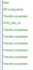
printf("Transfer completed.");
}
/**
* @brief Function for main application entry.
*/
int main(void)
{
uint32_t err_code;
const app_uart_comm_params_t comm_params =
{
RX_PIN_NUMBER,
TX_PIN_NUMBER,
RTS_PIN_NUMBER,
CTS_PIN_NUMBER,
UART_HWFC,
false,
NRF_UART_BAUDRATE_115200
};
APP_UART_FIFO_INIT(&comm_params,
UART_RX_BUF_SIZE,
UART_TX_BUF_SIZE,
uart_error_handle,
APP_IRQ_PRIORITY_LOWEST,
err_code);
bsp_board_leds_init();
printf("\r\nStart: \r\n");
nrf_drv_spi_config_t spi_config = NRF_DRV_SPI_DEFAULT_CONFIG; //SPI master driver instance configuration
spi_config.ss_pin = SPI_SS_PIN;
spi_config.miso_pin = SPI_MISO_PIN;
spi_config.mosi_pin = SPI_MOSI_PIN;
spi_config.sck_pin = SPI_SCK_PIN;
spi_config.frequency = NRF_DRV_SPI_FREQ_2M; // data rate: 2 Mbps
spi_config.mode = NRF_DRV_SPI_MODE_3; // SPI mode: SCK active low, sample on trailing edge of clock.
nrf_drv_spi_init(&spi, &spi_config, spi_event_handler, NULL); //Function for initializing the SPI master driver instance
printf("\r\nSPI config done! \r\n");
APP_ERROR_CHECK(err_code);
init_lis();
uint8_t read_data_1 = nrf_drv_spi_transfer(&spi, LIS3DH_WHO_AM_I_REG, sizeof(LIS3DH_WHO_AM_I_REG), read_data, sizeof(read_data));
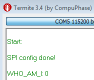
printf("\r\nWHO_AM_I: %x\n", read_data_1); //value: 0x11 ??
/*
nrf_drv_spi_transfer(&spi, LIS3DH_WHO_AM_I_REG, sizeof(LIS3DH_WHO_AM_I_REG), read_data, sizeof(read_data));
printf("\r\nWHO_AM_I: %x\n", read_data[1]); //value: 0x0 ??
*/
}
/** @} */
Here I get the value "0x11" instead of "0x33":
 uint8_t read_data_1 = nrf_drv_spi_transfer(&spi, LIS3DH_WHO_AM_I_REG, sizeof(LIS3DH_WHO_AM_I_REG), read_data, sizeof(read_data));
    printf("\r\nWHO_AM_I: %x\n", read_data_1);  //value: 0x11 ??
And here I get the value "0x0" instead of "0x33":
nrf_drv_spi_transfer(&spi, LIS3DH_WHO_AM_I_REG, sizeof(LIS3DH_WHO_AM_I_REG), read_data, sizeof(read_data));
printf("\r\nWHO_AM_I: %x\n", read_data[1]);  //value: 0x0 ??
Thanks in advance,
Christoph