Hi everyone,
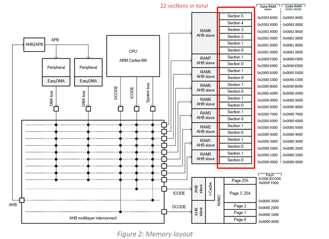
I am trying to understand the Memory layout of nRF52840 SOC in order to apply RAM retention into specific section. Looking the memory layout at pg 21 of the datasheet I can see 9 x ARM AHB slaves with total of 22 sections.

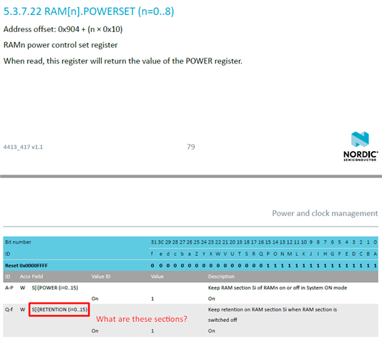
Then on pages 79-80 is the RAM[n].POWERSET register. In order to retain a memory section you have to write this register. I am very confused regarding the sections. The memory layout shows 22 sections, while the RAM[n].POWERSET register has 16 sections (A-P) for the RAM sections to be retained and accessible during System ON and 16 sections (Q-f) for the RAM sections to be retained during System OFF
The sections on the memory layout do not related with the sections on the register? For example, section 17 (R) of RAM[n].POWERSET register, to which section in memory layout does it correspond?

Also what is the difference between RAM[n].POWER (n=0..8) & RAM[n].POWERSET (n=0..8) registers?
Thanks in advance
Nick


