This post is older than 2 years and might not be relevant anymore
More Info: Consider searching for newer posts

Thingy91 Power consumption

Hi Dev team,

I am working around with the Thiny91 and wanted to have more information regarding the power consumption characteristics of the board.

I have a program running on the Thingy91 that connects to my server to send sensor data through MQTT, every 5 mins. In the meantime, I want to go into the lowest power consumption mode and wake up only to send data and then back to the low power mode in between.

I currently have a power consumption of around 1.5 mA in the low power mode and I want to reduce it further to the datasheet values. I also have enabled PSM mode with : 

CONFIG_LTE_PSM_REQ_RPTAU="10101010"
CONFIG_LTE_PSM_REQ_RAT="00000001"

and I see that it is configured by the network correctly as well. 

I had a few questions regarding the power consumption of the Thingy91 board :

(1). I get sensor data through my UART every 5 mins, so I cant have CONFIG_SERIAL = n in my prj.conf . That maybe 1 cause for this significantly high power consumption. Can I enable and disable the UART in runtime and will that make any difference to the power consumption in this case.

(2). The Thingy91 user guide says that , the 3.3V power domain can be powered down to save power when Thingy91 is in sleep mode. How can this be done ?

(3). Will it be logical to turn off the modem in order to save power during the sleep mode ?  

(4). Does modem firmware affect the power measurements ?

(5). To measure power power consumption, I use Joulescope and remove the USB power to the Thingy91. Thus, I am unable to view the logs in my link monitor when measuring power. Is there any other way to view the logs while measuring current (like Segger RTT Viewer) and how do I enable that .

(6). Any other power saving tips that could help reduce power for the Thingy91.

Regards,

Adeel. 

  • Hi Stian,

    Sorry for the late reply as everyone was busy in their holidays. I tried this approach of building the connectivity bridge application on nrf52840 but couldn't see any reduction in current. It still is around 120uA. I am assuming this 120uA is also because of the inbuilt sensors present on the Thingy91.

    I am measuring directly on the LiPo power input through Test pads TP13 and TP16. I am assuming that the current I measure there is the total current of the board (nrf9160 + nrf52840 + external sensors on the board). Can I also turn off the environmental sensor (bme680) and the accelerometer as well just to test if the current does go down through this ? If yes, can you let me know how to do this. 

    Regards,

    Adeel.

  • Hi Stian,

    I was looking more into this and I found a post regarding putting nrf52840 in deep sleep state.

    https://devzone.nordicsemi.com/f/nordic-q-a/57606/thingy-91-deep-sleep-firmware-for-nrf52840

    Can I use this approach to put the nrf52840 in deep sleep state, and if so, where do I add the code ? Can I add it in the System Off example that I am building for nrf9160 or any other specific example for nrf52840 ?

    As per my understanding till now, the extra current I am measuring could be due to nrf52 consuming current along with the environment sensor and accelerometer and I don't need these in my application now. So, I want to turn off these things to see the changes in current consumption.

    I really appreciate your help on this so far :).

    Regards,

    Adeel.

  • Hi Stian,

    I was trying to move ahead with the current measurement. After digging in more, I tried to measure the current through nrf9160 and nrf52840 separately to get an idea about the extra current I am seeing.

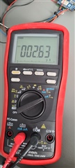
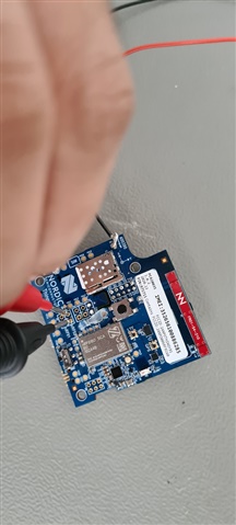
    I used the method in the Thingy91 user guide: Cut the solder bridge SB3 and measured current through multimeter for nrf9160.

    It was 2.6uA which is excellent.

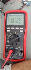
    Then I cut SB4 and measured current for nrf52840.

    I got a pretty high value that I do not understand.

    I have the connectivity bridge application running in the nrf52840 and the blinky example in nrf9160. 

    Could you help me in understanding what is causing such high current in nrf52840 measurement. 

    Could you also provide me your merged.hex file that you have uploaded in your nrf52840 board so I could try that out.

    Regards,

    Adeel.

  • Hi, the sensors connected to the 1.8V domain has to be powered as well because the nRF91 uses the 1.8V regulator on it's GPIO VDD input. So there's not an easy way to remove the power to them without cutting the VDD traces.

    I see that the current to the nRF52840 is about 2.0 mA. This is expected when the USB cable is plugged in. As soon as you pull out the USB cable, the UART and USB interface will shut down and the nRF52840 will go into system OFF mode.

  • Hi Stian,

    I see that the current to the nRF52840 is about 2.0 mA. This is expected when the USB cable is plugged in. As soon as you pull out the USB cable, the UART and USB interface will shut down and the nRF52840 will go into system OFF mode.

    I measured this current while the USB cable was unplugged. I did not have the USB cable plugged in.

    I had just powered my board through a 3.5 V supply on TP13 to the LiPo power input and did not have anything else connected to the Thingy.

    Is there something else that I am missing here ? 

    Regards,

    Adeel.

Related