This post is older than 2 years and might not be relevant anymore
More Info: Consider searching for newer posts

Nrf9160 GPS long time to fix with healthy RF electronics

Helo Nordic support team,
I am supporting a client that has designed a product using the NRF9160 with GPS. The product has a small patch antenna mounted on the pcb board, a saw filter and a LNA upstream the GPS port of the NRF9160.

The product has been tested extensively in the open and they experience long time to fix - in some cases 10 to 15 minutes from cold start (and some time no fix at all). It was suspected that the antenna gain and match could explain long fix time due to lov SNR for the received GPS signal. The antenna match was investigated using a network analyser and found to be around -10dB RL for the GPS band.

We have compared the product respons with a Thingy:91 using a larger patch antenna with integrated LNA. This gave similar results with long time to fix (not tested as thorough as the product).

Next test was done in a lab version of an anechoic chamber called GTEM cell. It is not a perfect environment for antenna performance tests but gives a good indication on performance. Using this GTEM device with a signal source we were able to apply a -90dbm CW signal to the product (now running only with test software and battery power). The test software logged the SNR and RSSI using the AT AT%XRFTEST=2,1,-90 at command and after the test we extracted the data from the product to a log file using a J-link SEGGER with RTT Viewer. We did a similar test with the Thingy:91 with the external antenna and got similar results.

Our preliminary conclusion is that the product (and the Thingy:91) has good RF performance (around 14dB gain including LNA, SAW and antenna gain).

I tend to conclude that the long time to fix can be explained by software. 

There are no other use of the radio between GPS read, the LTE is not used.

Can the Nordic team comment on why do we experience long time to fix from cold condition even with apparently healthy RF electronics ?
Thanks,
Regards
Bjørn
  • Hi, (18.3.2021)

    We added some more test, this time of the original GSP product with standard LNA (3dB lower compared to the previous test).

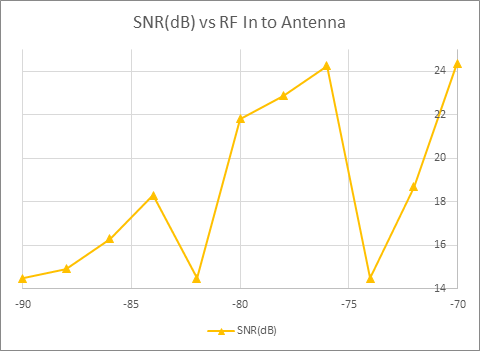
    The product is located in the GTEM test chamber and with RF power to the antenna from -90dBm and increased to -70dBm. The purpose is to check if the LNA or NRF9160 hits saturation at a certain RF input power level.

    These tests where run with AT command «at at%xrftest=2,1,-75». Some tests where repeated with the highest input power and with «at at%xrftest=2,1,-55».

    Pin (dBm)

    SNR

    RSSI

    SNR(dB)

    RSSI(dBm)

    -90

    232

    -19155

    15

    -75

    -88

    239

    -18254

    15

    -71

    -86

    261

    -17804

    16

    -70

    -84

    293

    -17333

    18

    -68

    -82

    232

    -16863

    15

    -66

    -80

    349

    -16392

    22

    -64

    -78

    366

    -15911

    23

    -62

    -76

    388

    -15391

    24

    -60

    -74

    232

    -15020

    15

    -59

    -72

    299

    -14870

    19

    -58

    -70

    390

    -14760

    24

    -58

    Testet with XRFTEST=2,1,-75


    SNR at the highest input power gave some strange data. Hence the test was repeated with the highest input power levels but with XRFTEST=2,1,-55.

    Pin (dBm)

    SNR

    RSSI

    SNR(dB)

    RSSI(dBm)

    -74

    401

    -14877

    25

    -58

    -72

    400

    -14376

    25

    -56

    -70

    418

    -13875

    26

    -54


    THINGY TESTS:

    The last test I did was on the Thingy with external antenna, , SAW and LNA. Antenna type Taoglas 574R. The J2 is connected to the extern

    Pin (dBm)

    SNR

    RSSI

    SNR(dB)

    RSSI(dBm)

    -90

    261

    -19706

    16

    -77

    -85

    337

    -18555

    21

    -72

    -80

    412

    -17313

    26

    -68

    -75

    472

    -16041

    30

    -63

    -70

    371

    -14970

    23

    -58

    It has been demonstrated in earlier posts that the Thingy GPS has somewhat better GPS performance. But from these test it is not super clear why. We have seen that the external antenna used on the Thingy has better Xpol performance compared to the Product. A good Xpol antenna will give 3dB for free compared to a linear receiver antenna.

    Thank you for your support on this case Jonathan.

    Regards

    Bjorn 

  • Hi Bjørn,


    One thing that sticks out is the dips/drops that you experience. R&D replicated a the test and could not reproduce the results.

    The result is perfectly aligned with thingy results –  the SNR gets better as the signal level increases.

    There is 15.5dB headroom in the Gain control design, so it is expected that SNR starts to get worse after -60 (if -75 is used in AT command and SIP input sees -75 dBm too), but all the way from -75 to -60 it seems to get linearly better if tested like this with cable (which seems to have about 1.5 dB loss).  Since I don't have LNA on board the signal generator has 15 dB power more than the customer.
     

    Signal Gen dBm AT cmd SNR RSSI
    -77 -75 409 -20037
    -76 -75 425 -19796
    -75 -75 439 -19546
    -74 -75 453 -19286
    -73 -75 463 -19055
    -72 -75 481 -18775
    -71 -75 486 -18535
    -70 -75 505 -18284
    -69 -75 515 -18004
    -68 -75 534 -17764
    -67 -75 539 -17513
    -65 -75 561 -17013
    -63 -75 571 -16512
    -61 -75 579 -16001
    -59 -75 593 -15471
    -58 -75 583 -15230


    So other then the dips the results you have is not bad, so on thing that might be a cause of this difference is the tuning of the antenna. Have you tested, tuned and matched the antenna with propper RF equipment ?

    Regards,
    Jonathan

  • Will add a comment;

    After more internal testing from our engineers the results seems to point out hat you might ave a sub-optimal antenna design.

    • Customer's Ext-LNA + Antenna seem to give about 15...17dB gain (is it expected result with given antenna gain+ LNA gain?), which is close internal HW Ext-LNA (SKY65943-11) gain derived from RSSI rise w/ and w/o Ext LNA
    • From conducted results SNR 22.5dB at -90dBm compared to customer's radiated data SNR ~15dB at -90dBm ant power: Customer DUT's SNR missing several dB's, which could be explained by noise coupling to GPS antenna or antenna gain (again antenna gain/efficiency and LNA gain would be good to know)
    • Test with internal HW show that Ant pwr level vs SNR with and without external LNA behave as expected i.e. no SNR dips with external LNA and total RX SNR is maintained nevertheless SIP's NF rise due to AGC steps (that is important if very high gain Ext-LNA is placed in GPS frontend)
    • These CW tests are just to check RX path validity and check possible unwanted noise, true GPS signal at DUT antenna lies well below thermal noise <-113dBm/1.023MHz which is amplified by ext-LNA before RFIC

    So our recommended prosess for designed new HW is as follows.

    1) Conducted RF performance verification in lab: verify HW path from antenna feed to nRF9160 SIP GPS input is performing as expected in terms of ext-LNA control, in/out matchings and impedance control of routing. 

    2) Passive GPS antenna measurements: measure antenna radiation pattern and efficiency (=aka passive antenna measurements) to understand a bit how the device might perform. Do we have e.g. these results available?

    3) Combined performance: to verify conducted and antenna solution performance adds-up as expected when combined. Here e.g. EMI from other parts of HW design (LEDs, other active ICs,..) may cause new issues not detected in 1) nor 2). (in proper anechoic chamber = consistent/known environment)

    Input for such testing is given in https://infocenter.nordicsemi.com/topic/struct_nrf91/struct/nrf91_guidelines.html?cp=2_0_7 
      => https://infocenter.nordicsemi.com/topic/nwp_034/WP/nwp_034/nwp_034_rf_perf_test.html 
      => https://infocenter.nordicsemi.com/topic/nwp_033/WP/nwp_033/nwp_033_intro.html 


    Regards,
    Jonathan

Related