
Hi,
I want to generate a sine wave using the nrf pwm library and a timer CC instead of a delay that is used in the sine example here to get better accuracy.
It basically works but I keep getting strange "jumps" in the signal. Here is an image of the signal after an RC filter (5kOhm, 100nF).
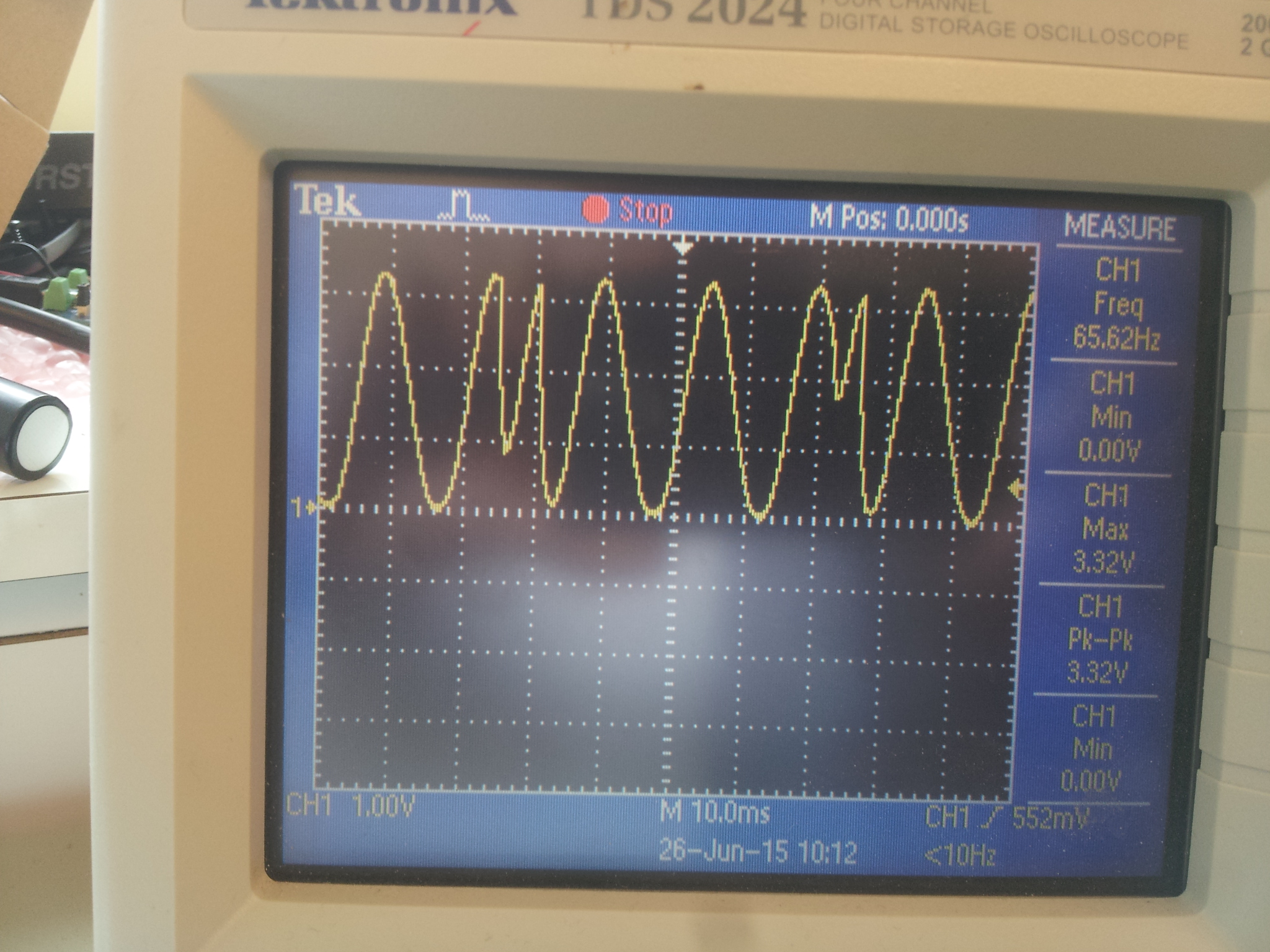
It seems like the phase variable changes value randomly sometimes and I cannot understand why.
Below is my code:
 #include <msp/ble-peripheral/BluetoothPeripheral.h>
#include <msp/drivers/delay.h>
#include <msp/drivers/board_ViTheSSG4rev1.h>

// timer stuff
#include <components/drivers_nrf/hal/nrf_gpiote.h>
#include <components/drivers_nrf/hal/nrf51.h>
#include <components/softdevice/s110/headers/nrf_soc.h>
#include <components/drivers_nrf/hal/nrf51_bitfields.h>

extern "C" {
#include <msp/drivers/nrf_pwm.h>
}

using namespace msp::drivers;

namespace {

uint8_t phase = 0;

bool active = false;

const uint8_t sine26[] = {0, 4, 16, 35, 59, 88, 120, 152, 182, 210, 232, 247,
    255, 255, 247, 232, 210, 182, 152, 120, 88, 59, 35, 16, 4, 0};

}

extern "C" {

void TIMER1_IRQHandler(void) {
  if (active) {
    nrf_pwm_set_value(0, sine26[phase]);
    if (phase < 26) {
      phase += 1;
    } else {
      phase = 0;
    }
  }

//pinToggle(LED_RED);

  NRF_TIMER1->EVENTS_COMPARE[0] = 0; // Clear compare match register

  NRF_TIMER1->TASKS_CLEAR = 1; // Reset timer

}
} // end of extern C

void initPWM(uint8_t pin, nrf_pwm_mode_t nrfPwmMode);
void initTimer(uint16_t frequency);

int main() {
  setupLEDPins();

  pinOutput(PIEZO_PWM_PIN);

// Init softdevice
  BluetoothPeripheral::instance().initialize();

// init pwm
//PWM_MODE_VITHESS_VIBRATOR is 0-255 (8-bit) resolution, 62.5 kHz PWM frequency, 16 MHz timer frequency (prescaler 0)
  initPWM(PIEZO_PWM_PIN, PWM_MODE_VITHESS_VIBRATOR);

  initTimer(128);

  pinClear(LED_GREEN);
  active = true;
  NRF_TIMER1->TASKS_START = 1;               // Start timer.

  while (1) {
    delayMs(1000);
    pinSet(LED_GREEN);
    NRF_TIMER1->TASKS_STOP = 1;
    active = false;
    nrf_pwm_set_value(0, 0);
    delayMs(1000);
    pinClear(LED_GREEN);
    active = true;
    NRF_TIMER1->TASKS_START = 1;               // Start timer.
  }

  return 0;
}

void initPWM(uint8_t pin, nrf_pwm_mode_t nrfPwmMode) {
  nrf_pwm_config_t
  pwm_config = PWM_DEFAULT_CONFIG;

  pwm_config.mode = nrfPwmMode;
  pwm_config.num_channels = 1;
  pwm_config.gpio_num[0] = pin;

// Initialize the PWM library
  nrf_pwm_init (&pwm_config);

// Start the external 16 MHz clock for a more accurate PWM frequency
  NRF_CLOCK->TASKS_HFCLKSTART = 1;
}

void initTimer(uint16_t frequency) {
  NRF_TIMER1->MODE = TIMER_MODE_MODE_Timer;  // Set the timer in Counter Mode
  NRF_TIMER1->TASKS_CLEAR = 1;  // clear the task first to be usable for later
  NRF_TIMER1->PRESCALER = 5; //Set prescaler. Higher number gives slower timer. Prescaler = X gives 16MHz/2^X Hz timer
  NRF_TIMER1->BITMODE = TIMER_BITMODE_BITMODE_16Bit; //Set counter to 16 bit resolution
//NRF_TIMER1->CC[0] = 500000 / (frequency * 26); //Set value for timer compare register 0, timer period is 2us, pwm period is (1/(freq*255)), pwm period/timer period is 15
  NRF_TIMER1->CC[0] = 150; //Set value for timer compare register 0 to 150 as test value

// Enable interrupt on Timer 1,for CC[0]
  NRF_TIMER1->INTENSET = (TIMER_INTENSET_COMPARE0_Enabled
      << TIMER_INTENSET_COMPARE0_Pos);
  sd_nvic_SetPriority(TIMER1_IRQn, 3);
  sd_nvic_EnableIRQ(TIMER1_IRQn);
}
Does anyone understand this behaviour?
Thanks!

