Writing a BLE, FreeRTOS program for nRF52833, getting unexplained BLE_HCI_CONNECTION_TIMEOUT

Hello everyone

I hope you all had a good start to the week.

I am stuck with an issue I don't quite get. 

I wrote code with BLE, FreeRTOS, and GPIOTE as a "proof of concept" for more complex code. 

It's a simple idea: a press on the button triggers a notification. I use nRFConnect, the Bluetooth Low Energy app.

- I ran it on the nRF52840-DK / S140 and it works

- I ran it on the EV-BM833 (Fanstel) which uses a nRF52833, and I lose connection with BLE_HCI_CONNECTION_TIMEOUT

(I changed RAM settings, mostly inspired by the example "ble_app_hrs_nfc_pairing_pca10100_s140", and it compiles and runs.)

I've faced similar issues (BLE_HCI_CONNECTION_TIMEOUT) when testing other code with the nRF52833, in general.

Looking at the following link, I'm wondering whether it's a matter of clock. Any other idea?

https://devzone.nordicsemi.com/f/nordic-q-a/29786/ble_hci_connection_timeout-and-nrf_clock_lf_xtal_accuracy_xx_ppm

Thank you in advance!

  • Hi run_ar

    Thank you for helping out.

    Using the RC, it worked on the module's evalboard (EV-BM833) and our custom chip.

    What do you mean by size? They are 0402, if it's the dimensions of the capacitors you're asking about.
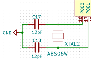
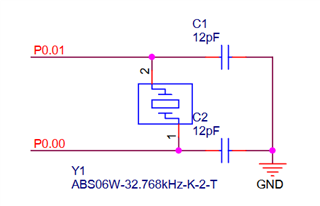
    I attached the schematics (1) of our chip / (2) of the EV-BM833. They're the same, and I'm observing the same "pathology" with our chip and the EV-BM833.

    I will check the signal strength but currently, I'm not moving the chips when I am testing and they are right next to the nRF52840 Dongle.


    Thank you again!

    Jerome

  • Hi,

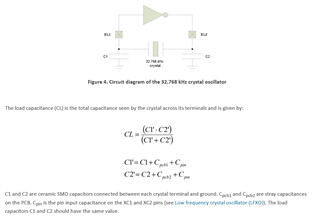
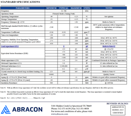
    Is this the load capacitors used by the module manufacturer? If my calculations are correct this will give a 8 pf load, while the specification for the crystal oscillator says you need a 3 pf load...

    Cpin

    Input capacitance on XL1 and XL2 pads

    4 pF

    Using the formula from above and adding Cpin to the capacitance (ignoring C_pcb) you will get (16*16)/(16+16)=8pF load.

    To get closer to 3 pf load you should use 2 or 3 pf load capacitors.i.e. using a 2 pf capacitor and adding the 4 pf pin capacitance gives (6*6)/(6+6)=3pF.

    Reference the crystal oscillator specification below to see the required load.

  • Good morning run_ar


    Thank you for your time and reply.


    I checked with Fanstel, they seem to "dispute the claim". I'll let the first prototype run with 500ppm but that's not too satisfying, in my opinion...


  • Ok, I could ask one of our Hardware experts to take a look at the crystal and matching components. But it seems the engineer you contacted is forgetting that the 32 kHz clock source is responsible for protocol timing, If the crystal is loaded incorrectly you will usually end up loosing the connection as the configured size of the listening window will be to small to handle the clock inaccuracy. (To be honest I am not sure what the actual accuracy of a crystal will be if it is not loaded correctly, but the frequency deviation can be signifiant) Yes, you can increase the PPM value to 500 ppm. But as you say that is not satisfying if you have a 20 ppm crystal. And for 500 ppm you might as well use the internal RC oscillator instead.

    Anyway, I think you said that your board works if you change to using the internal rc and 500ppm setting? Can you confirm you are not seeing this issue on any of your boards when using the internal RC oscillator?

    Does it still work if you change to crystall and 500 ppm? what if you decrease the ppm setting to 250, or 100? If I didn't misunderstand I think you said you still saw issues when using the external crystal and 500ppm? or at least at 100ppm?

Related