Continuous one sided drift in frequency measurement over GPIOTE.

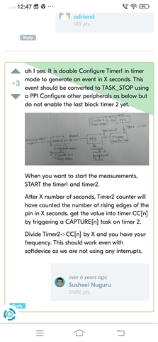
Using above strategy for frequency measurement. Frequency source connected with one gpio pin.

Only GPIOTE PPI Timer modules are involved

HFXO is in use full time through sd_...request command

Frequency observed is showing a one sided trend, which continues for day. A fix source of frequency is connected to gpio, below shared graph shows frequency tick counted on nrf side via gpio.
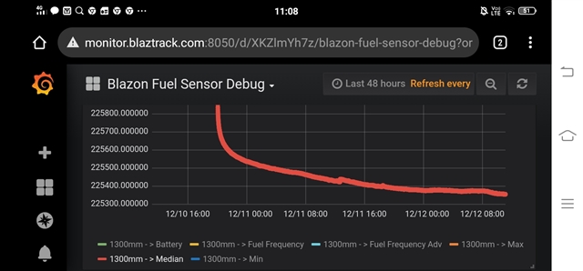
Same source of frequency, which is in production already, normally shows a minor drift which goes up and down w.r.t. day night temperature in a periodic manner.

Whole of implementation is following below reference

https://devzone.nordicsemi.com/f/nordic-q-a/9036/measuring-input-gpio-pin-frequency-with-soft-device-running

Unable to debug this behaviour, no interrupts are used, all the modules are interconnected via PPI module. All sources of drift , crystal, frequency generator should act according to ambient temperature. Which should be roughly periodic. Supply voltage is also plotted and their is no such one sided trend in that.


  • 1) is using interrupt handler not including soft side of nrf?

    2) plz comment on my strategy in previous comment, I can get rid of handler , and a timer also :). That would be more core cpu independent IMO.

    3) I agree nrf crystal is drifting , agree some silicon on frequency generator is drifting as well. But net result including both source side and destination side can't be one sided. Only variable is temperature , which is periodic during day and night, and expectation is net measurement drifting whichever side should show same pattern of up and down. Graph in original issue is of 3 day. Upper one went down continuously, lower one drifted both side. 

    Another thing if you look at second graph shared in comment, upper nrf graph is showing inflection at same points in time, where lower graph changed its direction. So drift contains a temp dependence but it's overshadowed by a monotonous downward trend.

  • Hi,

    thenagi said:
    1) is using interrupt handler not including soft side of nrf?

    I am not sure what you mean? If you ask if it could be interrupted/delayed by the SoftDevice, then yes, it can. That does not seem to be what is causing the issue here though as that could give you some odd measurements, but not a general  drift as you have shown. In any case, the SoftDevice generally needs a high interrupt latency, if you want to avoid this and don't need to sample regularly, you can use the timeslot API to do frequency measurements when the SoftDevice is guaranteed to not interrupt. I suggest waiting with this though, as it does not seem relevant for the current issue (frequency drift in one of the devices).

    thenagi said:
    2) plz comment on my strategy in previous comment, I can get rid of handler , and a timer also :). That would be more core cpu independent IMO.

    No, you cannot do that. My suggestion about using a single timer was caused my me reading the question too fast. You need two timers to measure the frequency, one in timer mode and one in counter mode, as you are doing, and as described in the old thread you linked to.

    thenagi said:

    3) I agree nrf crystal is drifting , agree some silicon on frequency generator is drifting as well. But net result including both source side and destination side can't be one sided. Only variable is temperature , which is periodic during day and night, and expectation is net measurement drifting whichever side should show same pattern of up and down. Graph in original issue is of 3 day. Upper one went down continuously, lower one drifted both side. 

    Another thing if you look at second graph shared in comment, upper nrf graph is showing inflection at same points in time, where lower graph changed its direction. So drift contains a temp dependence but it's overshadowed by a monotonous downward trend.

    I understand. But I do not see any way to explain this from your firmware implementation. I suggest you test the two devices separately (the NRF and whatever is the source of this frequency) using proper lab equipment to understand where the drift comes from (clock inaccuracy). That must be the way forward, as that will narrow down this issue a lot. Currently there is nothing indicating that the issue is related to the nRF or related circuitry at all (though it cannot be ruled out either - before you test this).

Related