Connecting ds18b20 to nrf9160dk

Hi, 

I am looking to connect the ds18b20 sensor to the nrf9160dk. I followed this post, but when I tried running it, I was getting a "create_nordic_project.py failed (1)" saying "error: cmake failed". 

I am a complete beginner when using the development kit so please bear with my questions. 

I have added "CONFIG_GPIO" in the prj.conf file, is there anything else I should be adding. 

Additionally, should I be making changes to the cmake file? The link above only mentioned the .c and .h file so I wasn't sure what else should be changed. 

If anyone could help me with this or could point me to resources that will help me solve this, I would really appreciate it. 

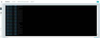
Update : The code is now running without any build errors but not printing any values. I had been using the hello_world sample to run it before which was giving the error, but then I tried switching to the blinky sample and running on that and it's building and running without any errors. (Would anybody know why this is).

My issue now is that it is not printing any values or anything to the Debug terminal on SES or the LTE Link Monitor. Does anyone know why this may be?

  • Update: I managed to get it printing values to the lte_modem. Ended up moving everything to the main.c folder, added the suggestion from this post and added in prj.conf::CONFIG_NEWLIB_LIBC=y and CONFIG_NEWLIB_LIBC_FLOAT_PRINTF=y. But now I am getting the same error as the original post that did this (I am getting the temperature as -0.062 every time.)

    Does anyone have any idea on how to fix this? I do not have access to a logic analyzer right now.

  • Hello Nandini,

    nrffan18 said:
    I'm assuming I should be adding it with the label "GPIO_0" since that was what was configured in the initial function in ds18b20.c file?

    My recommendation would be to connect the GPIO pin you would like to use to a LED on the nRF9160 DK first, as demonstrated in the Blinky sample. This way you can verify that the devicetree configuration of your application is correct. Afterwards, you can switch the pin direction and check if the sense mechanism works as expected.

    nrffan18 said:
    Does anyone have any idea on how to fix this? I do not have access to a logic analyzer right now.

    Since you would like to implement a sensor driver which not directly is integrated into the Zephyr RTOS, I recommend you to verify the dataflow on the configured pin with a logic analyser or oscilloscope.

    Regards,

    Markus

  • Hi Markus, 

    Thank you for the response. I apologize if the questions are repetitive. What exactly would I be looking for when examining the dataflow with the logic analyzer/Oscilloscope? I can get access to an oscilloscope so that might be mostly what I use. I am already aware that it is currently sending all the bits as 1 right now so what would be the next step in checking the data flow?

  • Hello Nandini,

    nrffan18 said:
    What exactly would I be looking for when examining the dataflow with the logic analyzer/Oscilloscope?

    I’m not familiar with the DS18B20 sensor myself, but if you look at the specification for the 1-wire bus (which you e.g. can do in this data sheet on page 10), you can find its requirements there.

    nrffan18 said:
    I can get access to an oscilloscope so that might be mostly what I use. I am already aware that it is currently sending all the bits as 1 right now so what would be the next step in checking the data flow?

    What you have to verify is that your driver layer sends data/bits according to this specification and that the nRF9160 GPIO sense mechanism is configured correctly in order to be able to receive data/bits.

    Regards,

    Markus

  • Hi, 

    Thank you for the feedback. Just to take care of any preliminary reasons, is it alright for me to be using pin 1 to read the sensor. And I currently havent changed anything in the device tree either, is the way I am configuring the gpio pin correct?

    Thank you for your help. 

Related