nrf52-DK 2.0.0 power consumption measurement

Hi Team,

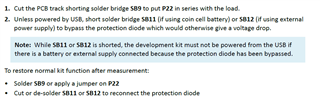
We have nrf52-DK with version 2.0.0 and we are trying to do power analysis for our application using it. We found a description in nRF52_DK_User_Guide on how to prepare the board for current measurement. (Cutting PCB Track of SB9 and cut SB11 or SB12). However, this description belongs to V1.2.x.

Is there any document that describes how to prepare nrf52-DK 2.0.0 for power measurement?

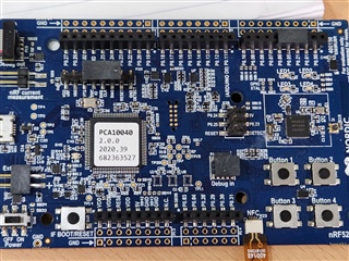
This is the kit that I've:

Thanks.

  • Hello,

    Its mostly same guidelines as like as other DKs' mentioned in our website.

    You can measure current in two mode source meter or ampere meter mode. 

    For source meter mode (https://infocenter.nordicsemi.com/topic/ug_ppk2/UG/ppk/measure_current_source_meter.html?cp=10_8_5_1 ), the vdd pin of ppk2 will connect to the positive pin of the nRF current measurement (p22) , Ground pin of PPK will connect to the negative pin of external supply (p21 on DK). 

    For ampere meter mode (https://infocenter.nordicsemi.com/topic/ug_ppk2/UG/ppk/measure_current_ampere_meter.html?cp=10_8_5_2), the Vin and Vdd pin of the ppk2 will connect to the negative and positive pin of the nRF current measurement consecutively. The ground pin will go to the negative pin of the external supply (p21).

    After setting the hardware you need power profile app  https://infocenter.nordicsemi.com/topic/ug_ppk2/UG/common/nrf_connect_app_installing.html?cp=10_8_5_5 and here you find how to use this application https://infocenter.nordicsemi.com/topic/ug_ppk2/UG/ppk/PPK_user_guide_Running_the_software.html?cp=10_8_6 to measure the current.

    I hope it helps.

    Thanks.

    Best Regards,

    Kazi Afroza Sultana

  • Thanks Kazi for reply.

    We are not planning to use the PPK but external Ampere Meter. For baseline, we are planning to measure the Deep Sleep current on nRF52 DK before we move on to our application profiling.

    So, to measure deep sleep current, we just modified the board: Cutting PCB Track of SB9 and soldered SB12.

    With a simple program that just returns from the main loop, we still see spikes (11uA) every 50 mS.

    void main() {
        return;
    }

    We are using nRF Connect SDK 1.8.0 based application and expecting the Deep Sleep current to be 1.9uA.

    P.S. Already disabled log and serial:

    CONFIG_LOG=n
    CONFIG_SERIAL=n
    Any direction on what could be the reason for those 11uA?
    Thanks!
  • Hi Kazi,

    Let me add more details for clarity.

    We are trying to baseline the deep sleep power consumption of nrf52832 using nrf52-DK.

    Setup:

    • nrf52-DK (2.0.0) modified for Power Measurement (Cut PCB Track of SB9 and soldered SB12), supplied using external supply
    • DAQ970A used as Ampere meter and connected to nrf52-DK on P22

    Code: Used zephyr\samples\basic\blinky as a base and modified following things:

    • In prj.conf added following:
      CONFIG_LOG=n
      CONFIG_SERIAL=n
      CONFIG_PM=y
      CONFIG_PM_DEVICE=y
    • In main() included following header files and modified delay for blink to 10 SB12
      #include <pm/pm.h>
      #include <device.h>
    • Added overlay file (nrf52dk_nrf52832.overlay) and disabled all unused peripherals.

    Code zip for reference: 6735.blinky.zip

    Results:

    Baseline current reading is 0.7uA and then every 50 milli seconds there is a spike of 11 uA as showing in the image below.

    There is a spike every 10 seconds, which is understandable since we have 10 seconds delay in main while loop.

    Also checked that system is going into idle state using Ozone.

    Can you please help with following queries?
    - what might be causing those 11uA spikes every 50 mS?
    - Is there any verified Firmware which can just blink an LED for couple of seconds and then puts system into deep sleep? (we should expect the current consumption of 1.9uA as per the datasheet)

    Thanks!

  • Hello,

    It is normal to get spikes in every 50 ms because the way regulator is designed. It means regulator is in refresh mode. When measuring an ampere meter over the current measurement header there will have to power with a clean supply on the external supply header and unplug the refresh mode. 

    You can find an explanation of refresh mode here https://devzone.nordicsemi.com/guides/cellular-iot-guides/b/hardware-design/posts/getting-started-with-current-measurements-on-the-nrf9160.

    There are several ways of measuring the current consume d by the nRF9160 SIP. Using a dedicated power analyzer is usually the preferred way, as it is often able to accurately measure and plot current draws with a large dynamic range, because of automatic range switching, and with a good time resolution.

    There is a chapter called refresh mode in that blog. It's written for nRF91 but it's the same for the 52 series mode. 

    what is the average current of their measurement including the refresh spikes? It should be about 1.9uA as per the datasheet. If the average current is closer to 10 uA, it's probably the USB noise issue and you need to use an external voltage supply instead.

    Thanks.

    Best Regards,

    Kazi Afroza Sultana

  • Hi Kazi,

    Thanks for the response. I believe, we have baseline sleep current as per expectation with avg around 2uA. With floor current around 800nA and spikes of around 5uA.

    However, we have weird issue where we now we have elevated current once we wake-up from timer (1 minute) and goes back to sleep. Here is the sequence we are testing:

    1. Init GPIO

    2. Turn on LED in main, sleep for 1 second, turn OFF the LED

    3. Start timer that wakes up every 1 minute

    4. Return from the main

    5. In timer Handler add work queue and return

    6. In work task, Turn LED ON, sleep for 1 second, turn OFF LED, return

    At step-4, after turning OFF the LED from the main and waiting for timer to start, we have current consumption of ~2uA (floor 800nA, spike 5uA, every 30mS)

    After Step-6, after turning OFF the LED current consumption increases around 28uA (of course with +5uA spikes) and keep on decreasing till the next cycle kicks in.

    Points to note:

    - When we turn OFF LED from the main then return, we have base current so definitely it's not an LED that's causing the leak

    - It happens only after wake-up and then sleep cycle

    Could you suggest what could be wrong here or direction to debug this?

    We are using nRD52832 custom board with nRF Connect SDK 1.8.0.

    Thanks!

Related