nRF9160 Low Power

Hi, 

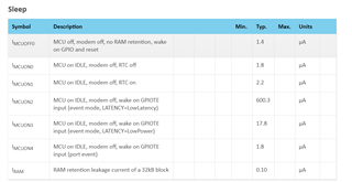
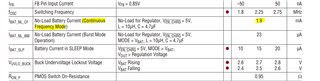
We are battling to get to the advertised low power values as described here: 

https://devzone.nordicsemi.com/guides/cellular-iot-guides/b/hardware-design/posts/measuring-psm-idle-current-on-the-nrf91-dk

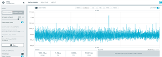
On our custom board, we average ~0.9mA with only the nRF9160 powered up, running the firmware linked in that post (7411.merged.hex)  and a 3.7V supply. 

We are running modem firmware 1.3.1. and testing using the PPK2 in source meter mode.

Our application firmware is based off of asset_tracker_v2 and running on ncs 1.5.1; we get similar results. prj.conf and schematics attached. 4087.Schematic Prints.PDF4555.prj.conf

Any help getting the sleep current down is appreciated. 

Kind regards

Dan

  • Hi Dan, 

    danimalia said:
    I tried on another unit with the same results (2 units in fact). 

    Great to know. 

    danimalia said:
    I also removed the LNA, did not make a difference.

    Thanks for checking. 


    danimalia said:
    PPK is attached

    Thanks.


    The unusual high current draw does seem to point to that something else is powered in addition to the nrf9160, all other IC's of relevance should have been removed. 

    In you .conf file you do have logging enabled, and SERIAL is not explicitly disabled, have you seen the overlay-low-power.conf in the asset tracker example? 

    Could you test your application with the following in .conf

    # Disable serial interface.
    CONFIG_SERIAL=n
    
    # Disable LEDs
    CONFIG_LED_CONTROL=n
    
    # Disable UART console.
    CONFIG_UART_CONSOLE=n
    
    # Disable event logging.
    CONFIG_APP_EVENT_MANAGER_SHOW_EVENTS=n
    
    # Disable AT host library.
    CONFIG_AT_HOST_LIBRARY=n
    
    # Disable logging
    CONFIG_LOG=n


    But if you where testing with the hex file from the blog post then this should not be the issue. 


    Update:

    Can you confirm that when you followed the process of "Checking your measurement setup" that you get the same value as in the blog post?

    You say: Your suggested thread gave me the same results and the attached PPK file is with the hex shared there: 1452.sysoff.hex 
    Do you mean that you get 0.9mA, as you show in the PPK2 file?

    You should see something that matches the sleep specs, so les then 2uA.
     https://infocenter.nordicsemi.com/topic/ps_nrf9160/_tmp/alta.nRF9160/autodita/CURRENT/parameters.id_current_sleep.html?cp=2_0_0_4_5_0_1 


    It is very important that you are able to verify the setup. 


    Update 2:
    The PMIC might be the culprit here. The mode pin in your design is pulled low to ground, this sets the PMIC in Constant-Frequency (PWM) Mode operation. From the data sheet:

    In this mode, it uses a current mode architecture including
    an oscillator, an error amplifier, and a PWM comparator
    for excellent line and load regulation. The main switch
    MP2 (P-channel MOSFET) turns on to charge the inductor
    at the beginning of each clock cycle if the FB pin voltage
    is less than the 0.8V reference voltage. The current into
    the inductor (and the load) increases until it reaches the
    peak current demanded by the error amp. At this point,
    the main switch turns off and the synchronous switch
    MN1 (N-channel MOSFET) turns on allowing the inductor
    current to flow from ground to the load until either the
    next clock cycle begins or the current reduces to the zero
    current (IZERO) level.


    Pulling the Mode pin high will put it in Burst Mode, this should reduce the current consumption.  

    You can tie the pin to one of the nRF9160 GPIO's and switch between BM and CF. 

    Might need to bypass the PMIC to get the same results as in the blog post, and confirm that it is the PMIC that is causing the unexpected current draw. 

    Regards,
    Jonathan

  • Hi Jonathan 

    Thanks for the detailed response - I'll reply in detail again tomorrow; but I think the PMIC may be the culprit as you've suggested. 

    Thanks

    Dan

Related