I use NCS version 1.9.1.i use the command line tool to build project and flash the executable file to my board.Both in Rx or Tx are nrf52833dk.
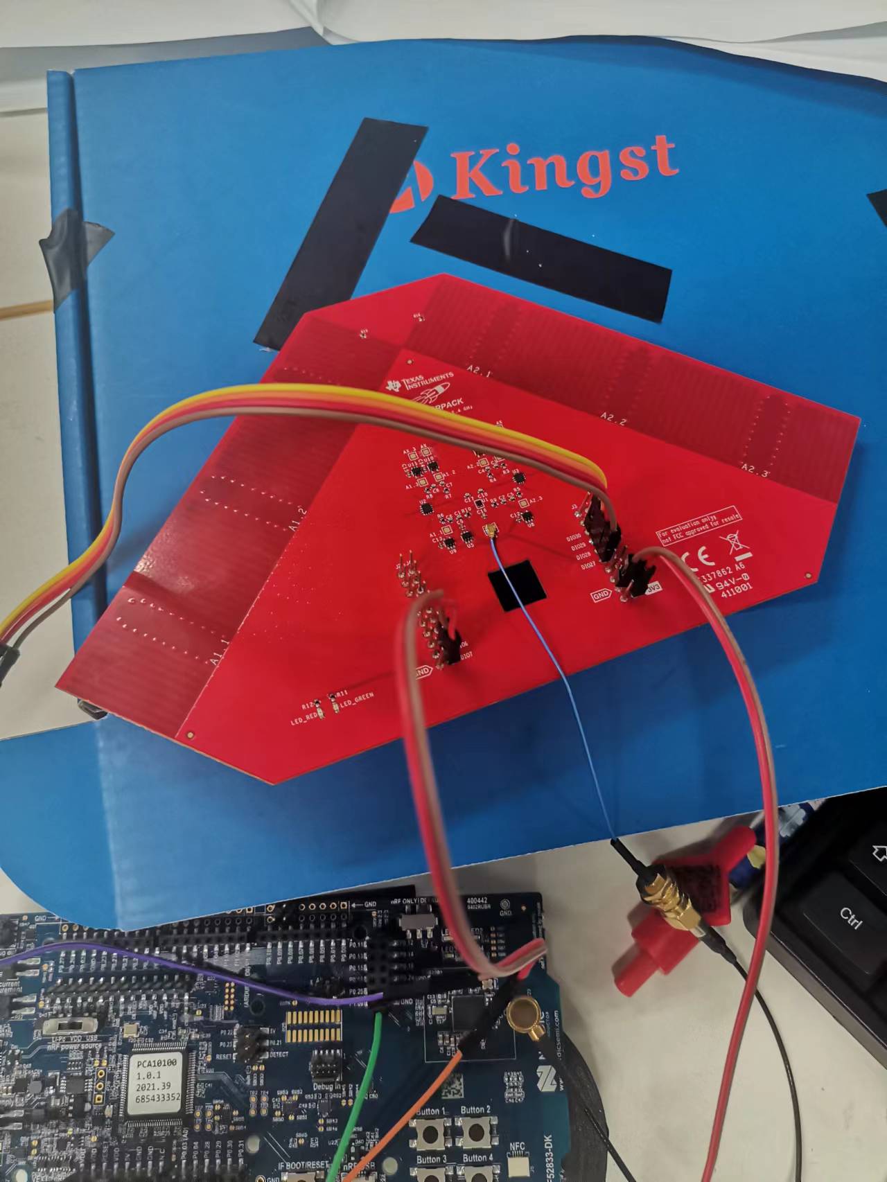
As you see that there are only six(6) antennae i can use.i use RTT to get debug or log.
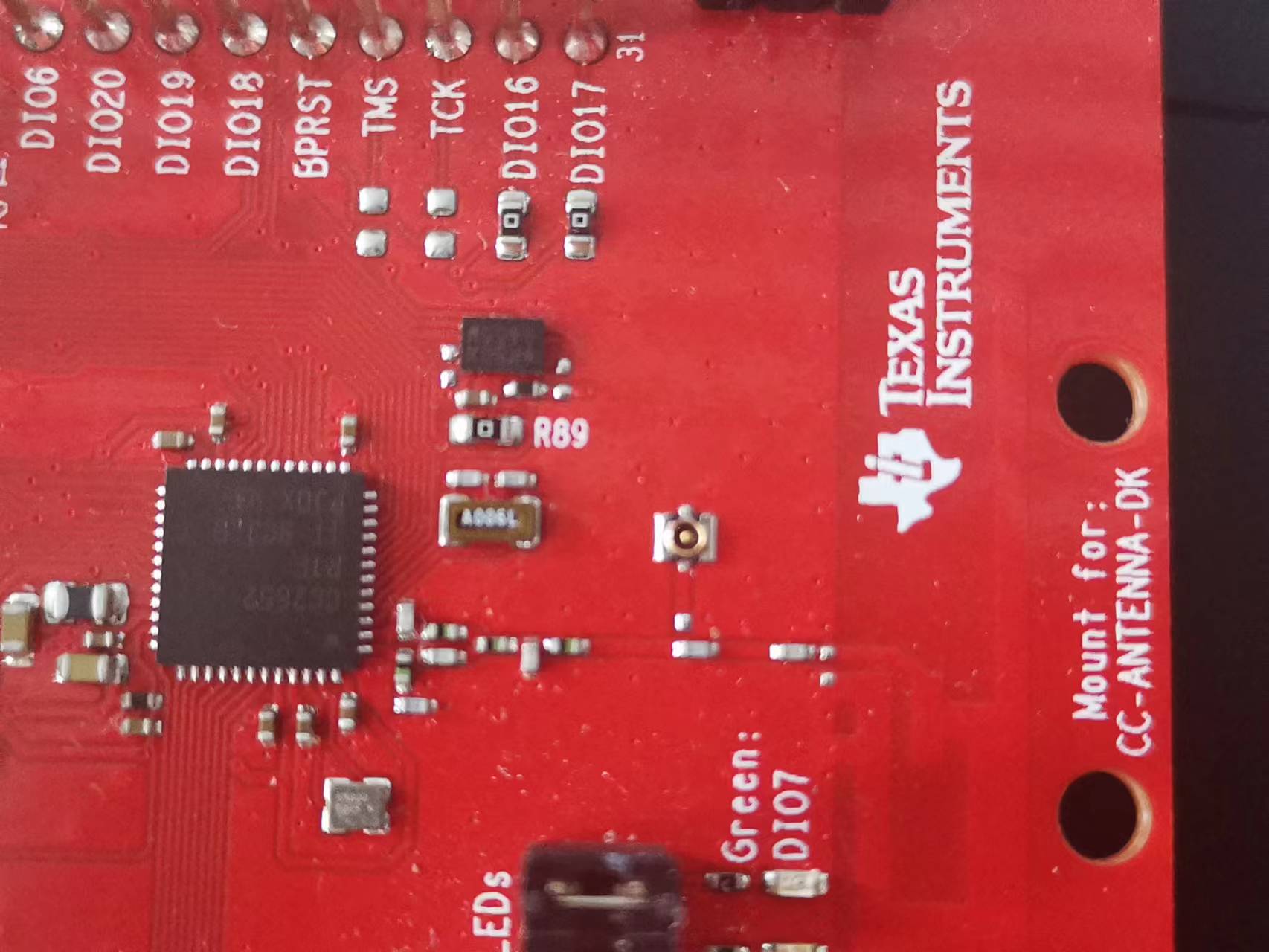
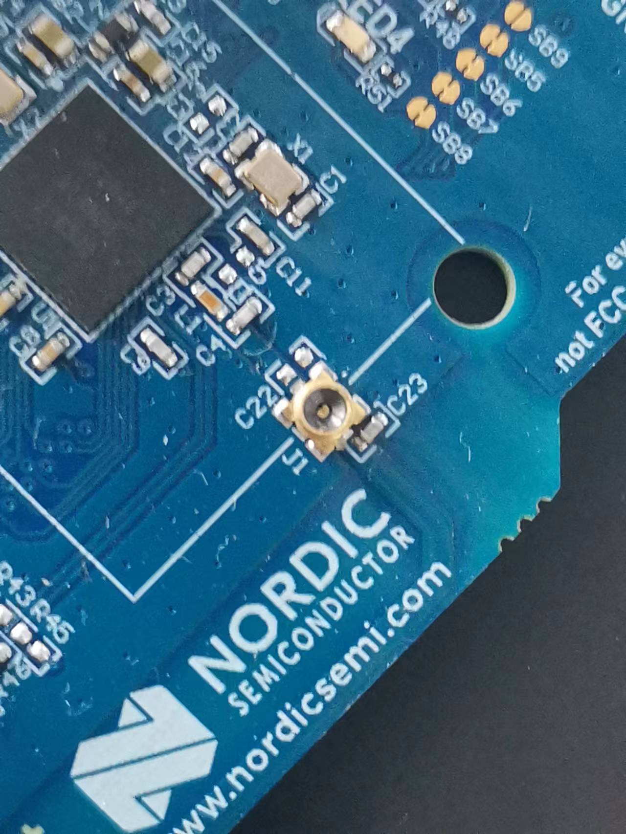
the next photo is my antenna board.
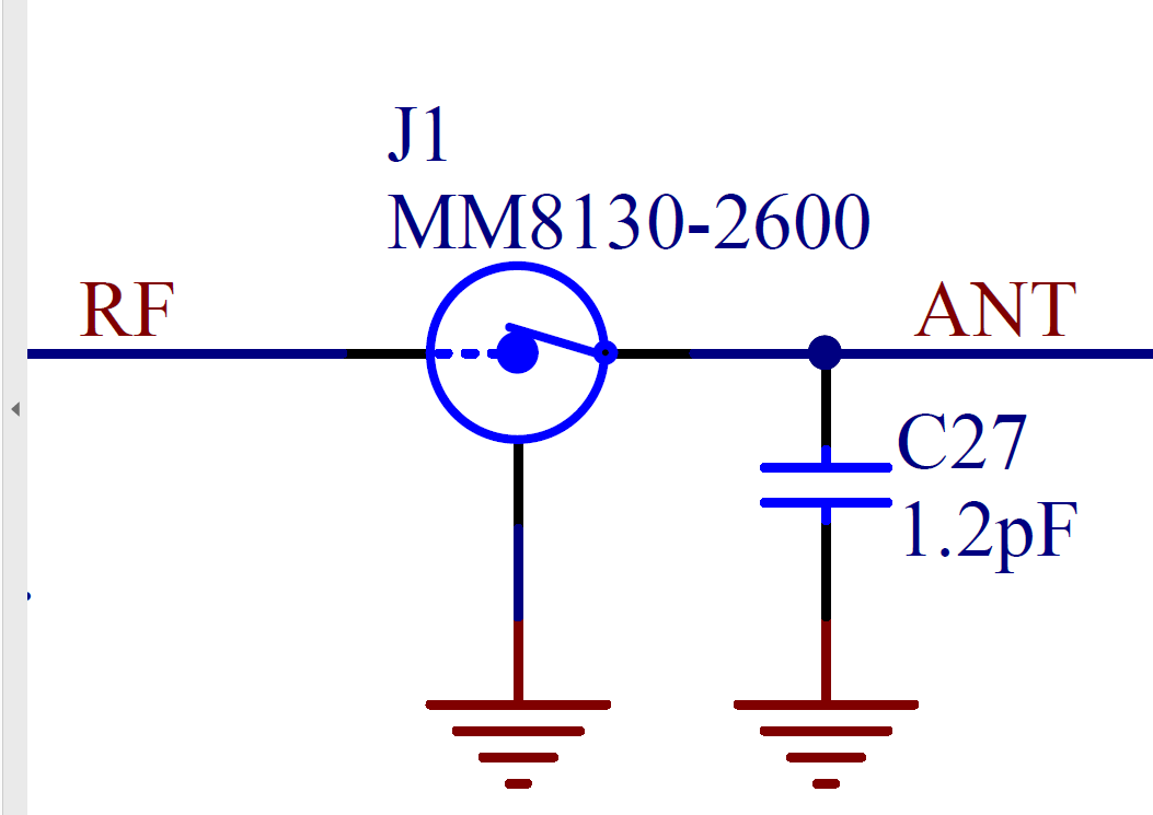
on the basis of silab 16 antenna array,i modify some configurations about this.
Firsly,i change the antenna _num which is refered to antennae numbers.At the same time,i change the dfu_antenna,the next is my configuration.
/*
 * Copyright (c) 2021 Nordic Semiconductor ASA
 *
 * SPDX-License-Identifier: LicenseRef-Nordic-5-Clause
 */

&radio {
	status = "okay";
	/* This is a number of antennas that are available on antenna matrix
	 * designed by Nordic. For more information see README.rst.
	 */
	dfe-antenna-num = <3>;
	/*dfe-antenna-num = <16>;*/
	/* This is a setting that enables antenna 12 (in antenna matrix designed
	 * by Nordic) for Rx PDU. For more information see README.rst.
	 */
	dfe-pdu-antenna = <0x4>;
	/*dfe-pdu-antenna = <0x0>;*/
	/* These are GPIO pin numbers that are provided to
	 * Radio peripheral. The pins will be acquired by Radio to
	 * drive antenna switching when AoA is enabled.
	 * Pin numbers are selected to drive switches on antenna matrix
	 * desinged by Nordic. For more information see README.rst.
	 */
	dfegpio0-gpios = <&gpio0 3 0>;
	dfegpio1-gpios = <&gpio0 4 0>;
	dfegpio2-gpios = <&gpio0 28 0>;
	dfegpio3-gpios = <&gpio0 29 0>;
};
Them i chnage the antenna partterns as follow in main.c file.i wnat to use three antennae.
#if defined(CONFIG_BT_DF_CTE_RX_AOA)
/* Example sequence of antenna switch patterns for antenna matrix designed by
 * Nordic. For more information about antenna switch patterns see README.rst.
 */
/*切换顺序,11,12,1,2,10,3,9,4,8,7,6,5  12根天线*/
/*static const uint8_t ant_patterns[] = { 0x2, 0x0, 0x5, 0x6, 0x4, 0x9,
*					0xA, 0x8, 0xD, 0xE, 0xC, 0x1 };*/
/*切换顺序,11,12,1,2,3,4,5,6,7,8,9,10 12根天线*/
/*static const uint8_t ant_patterns[] = { 0x2, 0x0, 0x5, 0x6, 0x1, 0x4,
*					0xC, 0x9, 0xE, 0xD, 0x8, 0xA };*/
/*切换顺序,1,2,3,4,5,6,7,8,9,10,11,12,13,14,15,16  16根天线*/
/*static const uint8_t ant_patterns[] = { 0x0, 0x8, 0x4, 0xC, 0x2, 0xA, 0x6, 0xE,
*					0x1, 0x9, 0x5, 0xD, 0x3, 0xB, 0x7, 0xF };*/
/*切换顺序,12,9  2根天线*/
/*static const uint8_t ant_patterns[] = { 0x0, 0xC };*/
/*切换顺序,A1.1,A1.2,A1.3  ,3根天线*/
static const uint8_t ant_patterns[] = { 0x4, 0x2, 0x1 };

#endif /* CONFIG_BT_DF_CTE_RX_AOA */
You can see it in last sce second line.The parttern are 0x4, 0x2, 0x1 .
Finally i add the RTT log for my project.i add some configurations about it in prg.conf
#RTT log
CONFIG_USE_SEGGER_RTT=y
CONFIG_RTT_CONSOLE=y
CONFIG_UART_CONSOLE=n
I can get the full output as rst file said in Tx.
The Tx is here.
00> *** Booting Zephyr OS build v2.7.99-ncs1-1  ***
00> Starting Connectionless Beacon Demo
00> Bluetooth initialization...success
00> Advertising set create...success
00> Update CTE params...success
00> Periodic advertising params set...success
00> Enable CTE...success
00> Periodic advertising enable...success
00> Extended advertising enable...success
00> Started extended advertising as DE:86:9B:6D:43:F0 (random)
The Rx have not full output.
Booting Zephyr OS build v2.7.99-ncs1-1  ***
00> Starting Connectionless Locator Demo
00> Bluetooth initialization...success
00> Scan callbacks register...success.
00> Periodic Advertising callbacks register...success.
00> Start scanning...success
00> Waiting for periodic advertising...
00> [DEVICE]: 20:B8:52:EB:41:3A (random), AD evt type 3, Tx Pwr: 127, RSSI -73  C:0 S:0 D:0 SR:0 E:0 Prim: LE 1M, Secn: No packets, Interval: 0x0000 (0 ms), SID: 255
00> [DEVICE]: 70:61:EE:22:88:0C (public), AD evt type 0, Tx Pwr: 127, RSSI -80  C:1 S:1 D:0 SR:0 E:0 Prim: LE 1M, Secn: No packets, Interval: 0x0000 (0 ms), SID: 255
00> [DEVICE]: DD:49:C2:60:5A:F8 (random), AD evt type 0, Tx Pwr: 127, RSSI -76  C:1 S:1 D:0 SR:0 E:0 Prim: LE 1M, Secn: No packets, Interval: 0x0000 (0 ms), SID: 255
00> [DEVICE]: 70:74:BB:30:FF:2F (random), AD evt type 3, Tx Pwr: 127, RSSI -67  C:0 S:0 D:0 SR:0 E:0 Prim: LE 1M, Secn: No packets, Interval: 0x0000 (0 ms), SID: 255
00> [DEVICE]: 2F:E8:97:E4:48:99 (random), AD evt type 3, Tx Pwr: 127, RSSI -79  C:0 S:0 D:0 SR:0 E:0 Prim: LE 1M
As rst file descrbled,the problen exist in success. Found periodic advertising.
I find it in main.c file,i can't solve this problem. it is controled by void main() in main.c file.
Code is here.
while (true) {
		per_adv_found = false;
		scan_enable();

		printk("Waiting for periodic advertising...\n");
		err = k_sem_take(&sem_per_adv, K_FOREVER);
		if (err) {
			printk("failed (err %d)\n", err);
			return;
		}
		printk("success. Found periodic advertising.\n");

		create_sync();
what do you think this problem?