debugging while using external supply on NRF52840-DK

Hi Nordic,

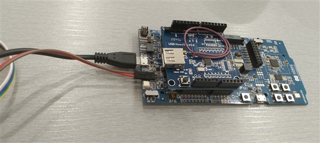
I want to use an Arduino USB host shield with NRF52840-DK. Since the VDD on DK is 2.5v and MAX3421 on the shield works with 3 to 3.6 volts, I have to use an external supply to power both boards.

Everything seems to work fine. However, when I try to connect the DK's J2 USB to debug my project, the VDD voltage decreases to about 2.5 volts, which shuts down the host shield.

Is there any other way than using an external debugger to stop the VDD voltage from decreasing?

BTW I didn't change any switch/jumper on the DK, and everything is on default mode.

  • Hi Swathy,

    Sorry for the late response.
    - A photo of my setup:

    - I use the J2 USB port to debug my project and connect the external power source to P21.

    - To test whether the board works with an external supply, I wrote a simple code to toggle one of the pins on the board ( one that has no connection with any peripherals on the board). This code worked fine when SW10 was off but didn't work when it was on.

    If there are any other switches or options related to this problem, please let me know to check them too so we can reach a solution.

    Bests,

    Hossein

  • Hi Hossein,

    I found a solution which might work for you. You can use the REG0 on the nRF52840 to output 3.3V. There is a voltage follower on the DK VDD that follows the nRF52 VDD when using high voltage mode. So by setting REGOUT0 to 3.3V, the VDD on the DK will also be 3.3V, and you can still use J2 for debugging.

    1. Write 5 to the REGOUT0 register
      • nrfjprog --memwr 0x10001304 --val 5
      • power cycle
    2. Plug in a USB cable to J3. (using two cables, both for J2 and J3)
    3. Set nRF power source switch to USB
    4. Check that the VDD voltage is now 3.3V
    5. Leave the other switches in their default position
      • SW10 to OFF
      • SW6 to default
      • Do not supply power to the external supply header
      • Make sure that SB40 and SB41 are not cut, or put a header on P22 and P23

    So what happens is that the nRF52 is powered from J3 at VDDH using the nRF power source switch. Then it outputs 3.3V to nRF_VDD. The VDD on the DK follows the voltage on nRF_VDD, so that the IO voltage is the same as on the nRF52 chip. The debugger is still powered from J2.

    Also maybe check that your software is not overwriting REGOUT0. Remember that in order to change the value on REGOUT0. UICR will have to be erased first, since it's part of the flash (nrfjprog --eraseuicr).

    Best regards,
    Stian

Related