This post is older than 2 years and might not be relevant anymore
More Info: Consider searching for newer posts

nRF51822 and battery low level detection

Hi,

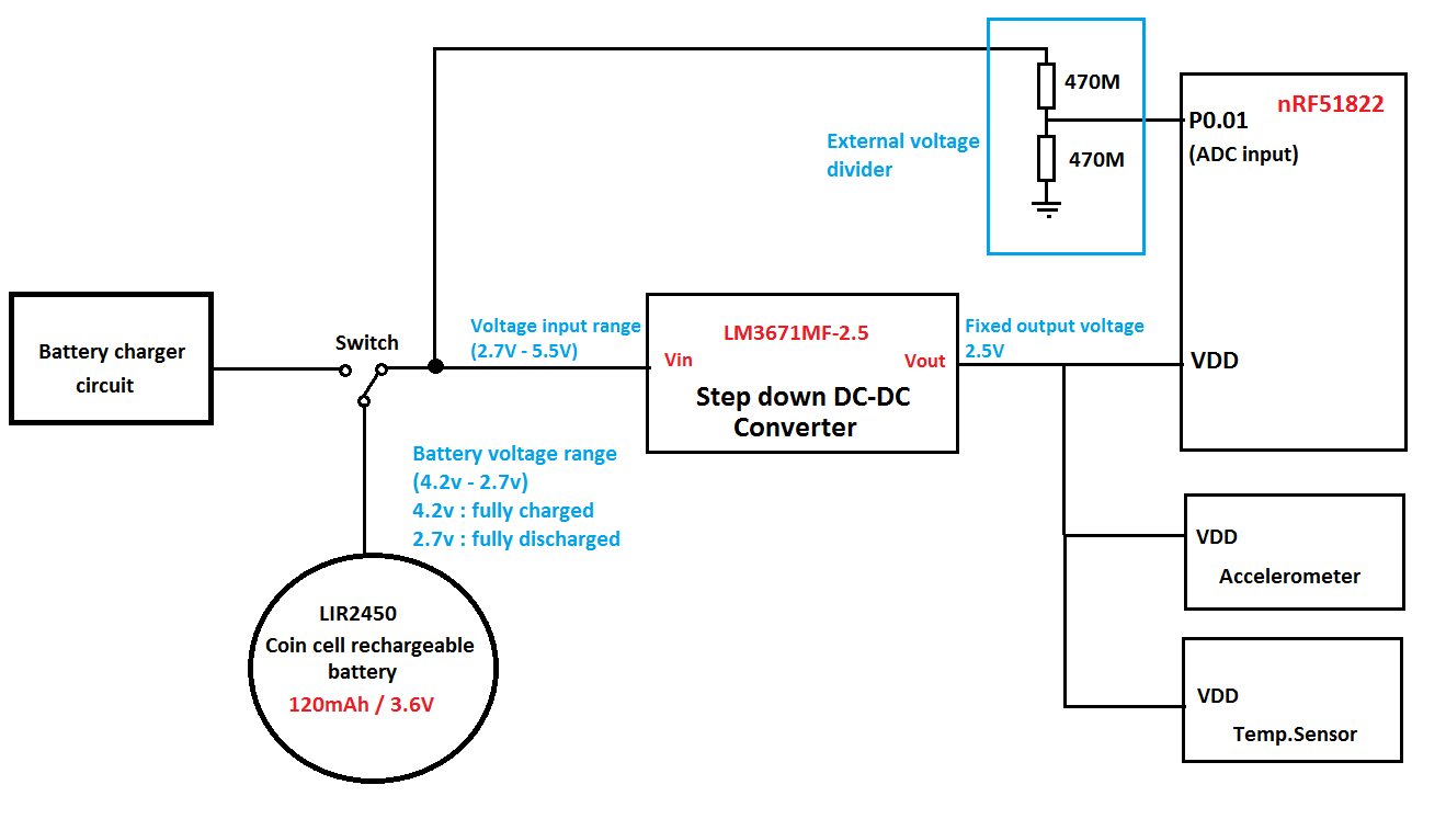
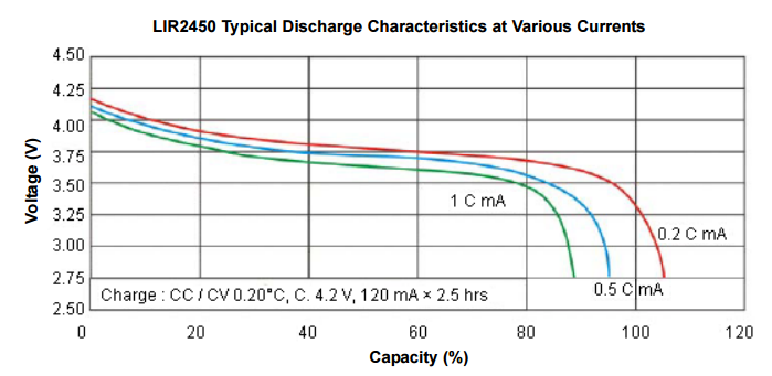
I'm making my own prototype board using the nRF51822. this board is powered by a rechargeable battery lir2450 (3.6V): www.powerstream.com/.../Lir2450.pdf

i want to know how can i make the nRF51822 chip know when the battery is low. i want something indicating me that the battery is being emptied like, led, Buzzer... .

I was thinking about using one of the ADC input of the nRF51822 to measure the voltage battery and when the voltage drop to a certain threshold that's mean the battery level is low.

But this is won't work because the ADC reference voltage will drop also as its powered it by the same battery.

so i want to know if the nRF51822 have an internal low battery detection or something like that which let me know that the battery level is low ?

Best regards,

  • When battery is fully charged it will have 4.2V. Look at the datasheet at the end of page 4 to understand how voltage linked to state of charge. Also you will need to have power supply to reduce 4.2V to 3.6V or less to supply to nRF. It will affect the efficiency of the system. Upd: You probably think that while charging and applying 4.2V to the battery you can disconnect nRF from high voltage and when charger unplugged battery will have nominal voltage 3.6V. It is not correct. Battery will have 4.2V after charger unplugged

  • Thanks for the answer Alex and Martin, i appreciate that.

    here's the schema that i made for the circuit:

    image description

    I/ as i'm using a rechargeable coin cell battery so the voltage varies from 4.2v when its fully charged to 2.7v when its fully discharged. we note that the battery voltage when its fully charged is above the maximum voltage supported by the nRF51822.

    image description

    So the only solution is to drop the voltage to 2.5V and to do that there are 2 slolution :

    • using a linear regulator. this is not a good idea because the efficiency is so bad. (4.2v-2.5v) * I = power dissipated in heat.

    • using a DC-DC converter. i find a good circuit the LM3671MF-2.5 , here's the datasheet : www.ti.com/.../lm3671.pdf

    the input voltage range is between 2.7 V to 5.5 V which is OK for the battery and the output voltage is 2.5V which is OK for all circuit (nRF51822, accelerometer, temp.sensor). the DC-DC converters are know by their good efficiency. but when i took a look at the "Efficiency vs. Output Current" curves in page 9 of the datasheet i notice that the Efficiency are bad for a low current.

    image description

    For example for Vin = 3.6v and current = 0.1mA the Efficiency = 74%. and as known the nRF51822 consume less current than 0.1mA. so the Efficiency will be lower than 74% (nRF51822 consume 2.6µA @ 3V ON mode, all blocks in idle mode) this is not good for the battery mainly when my objectif is to maintain the battery charge for a long time. this is a waste of energy. do you have another solution to drop the voltage with a good Efficiency and with a low current consumption ??

    II/ for the battery low detection i'm gonna use an external voltage divider to measure the battery voltage because the maximum battery voltage can reach 4.2v which is above the ADC threshold even with using a 1/3 prescaler.

    so the voltage divider consist of two resistor with high value (470M Ohm) to minimize at maximum the current consumed by the divider circuit. i (max) = 4.2v/ (470 M * 2 ) = 4.4 nA which is insignificant comparing to the battery capacity 120mAh . this circuit will divide the voltage to two. for example for 4.2V the divider will drop the voltage to 2.1V then i will use an internal prescaler of 1/2 to drop the voltage to 1.05V

    is this external circuit OK or there are a better other solution ?

    Thanks for help

  • Look at this chip. Quiescent current and efficiency at your current range is better. I couldn't find better converter for myself, will be happy to hear about more efficient chip. As for divider, you need to remember that input impedance of ADC is not that high and the Reference manual states that the output impedance of voltage source must be 1kOhm or lower. Check page 166. If you don't need to report state of charge of the battery and need only to catch event when battery voltage dropped below let's say 2.8V then I would use voltage monitor chip. If you need to know battery state at any time then Gas Gauge chip can be a solution but it is more expensive solution (need to program it as well).

  • thx alex, i find a good chip for low power energy the tps62736 : www.ti.com/.../slvsbo4c.pdf and it cost only 2.8$. and it can monitor the low voltage level of the battery, i'll keep you in touch.

  • @Tizana The tps62736 DCDC converter chip that you point to seems to be very suitable for nRF51 and lithium battery. You get the best efficiency if you program the output voltage of the DCDC converter to be close to the minimum nRF51 supply voltage of 1.8V. 1.9V would be a good output voltage for the DCDC converter to have a safe margin from the 1.8V minimum.

    Another thing. As Alex points out, you should have resistor values in the voltage divider optimally below 1kohm to prevent any ADC output error. A good method however to prevent error with higher resisitor values is to connect a capacitor between the ADC input and ground.

    Third thing. The resistor values in your voltage divider are very high. This might be adequate in your situation but your ADC input signal will be very vulnerable to any external noise. This blog post suggests perhaps more suitable voltage divider setup for measuring lithium battery voltage.

Related