AoA IQ Data soundness

Hi, I'm currently using the Direction Finding Connectionless examples to evaluate using the nRF5340 for numerous projects we have lined up, and I'm having difficulty ascertaining whether or not I'm actually collecting valuable data.

I've made minimal changes to the example, just set up the GPIO overlay to match the antenna array we are using and setting up a very basic switching sequence.

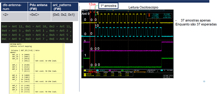
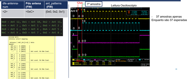
My overlay file is currently set to use 3 antenna, with 0x3 set as the reference antenna.

	dfe-antenna-num = <3>;
	dfe-pdu-antenna = <0x3>;

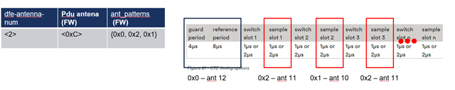
My switching sequence is then set to {0x5,0x9}.

My understanding then is that of the 45 samples I receive from the CTE, the first 8 would be using ANT 0x3, allowing me to ascertain a reference phase using arctan2(Q,I), then the remaining would alternate between ANT0x5 and ANT0x9. From the switching samples I calculate a phase offset and use the basic θ = arccos((ψλ)/(2πd)) formula to calculate an angle.

My first 2 most basic questions are so:

1. Obviously, this approach is going to struggle with noise and reflections etc, but I'm unsure as to how big those effects might be - how flakey I should expect this naive appraoch to be. 

2.  The IQ samples themselves, I'm unsure as to what range of values I should be expecting. In most of my testing so far the majority of my samples are in the range 0±50, which from looking around on this site seems to be low.

I'm reasonably confident the data I've collected so far is garbage, and will have more equipment available soon to properly interogate my hardware setup (WFH introduces some unfortunate delays at times), but I want to check it's not my analysis of the data that's the issue.

When calculating the reference phase, I use atan(Q,I) and see that odd samples are consistently ~180° out of phase with even samples. Is this expected behaviour, and if not how am supposed to ascertain the reference phase, are there supposed to be two reference phases for odd an even sample slots? My intuition is no but as I'm sure is obvious, I'm very much learning on the job here.

  • Hi Reubey

    1. Sorry about the "basic" information first. It seems I mistook your experience with Direction Finding initially. The switch pattern is set by the ant_patterns array in the main.c file. I'm not sure what "PDU" antenna pattern you refer to in the .overlay file, as the only things defined there by default are the number of antennas, the setting to set which antenna to enable for RX PDU, and the GPIOs used for antenna switching.

    2. The range of "good IQ values" is hard to define, as it depends on the use case, environment, antennas in the array, and number of antenna arrays in your application. From testing on our end with our 12-antenna array we've seen good IQ values up to 7-8 meters at trade shows where we have multiple other demos running and generally lots of interference from phones and computers, etc. In less noisy environments (if my memory serves me right) I think we've seen good IQ data at up to ~20 meters.

    I've also seen use cases where multiple antenna arrays are used, to give a cm accuracy in rooms up to 5x5 meters.

    Best regards,

    Simon

  • I've aquired a scope to be able to probe the GPIO pins and have been able to answer my questions about how the ncs sample uses the ant_patterns array. The first pattern is held for 12us, which corrolates with the Guard + Reference periods from the AoA spec. The antenna is then switched to the next pattern in the array, where the first (non-reference, 8 reference samples are taken in the aforementioned reference period) IQ sample is taken. The patterns array is then traversed by the software, and if the number of samples is greater than the length of the patterns array, the software will loop back to the first element in the patterns array, the same pattern used for the guard and reference periods.

  • I was going through the same difficulty. I used a oscilloscope to measure the gpios that control the switch pattern.  I bring an image of GPIOs measurements and the variable configuration to contribute.

    Upper left side are the antenna array configuration variables.

    The antenna used as PDU, is activated by default when outside the switching period as we can see "ant 9" in the figure.

    The first value in 'ant_patterns' is the antenna used to sample during the guard period+reference period as we can see 12us in the figure.

    The IQ sampling will occur in the other two antennas "0x2,0x1" of 'ant_patterns' for the example mentioned.

    In short, for this configuration, we have.

  • I think that the antenna pattern should include the pdu antenna,the pdu antenna should be placed first.Besides this,I have the sreen photo of six antennas.

  • I think that the antenna pattern should include the pdu antenna,the pdu antenna should be placed first.Besides this,I have the sreen photo of six antennas.

    The first antenna in 'ant_patterns' is used to guard period+reference period.

    If you use the PDU antenna in first of 'ant_patterns', this antenna first receive the PDU and after this is used to guard period+reference period. I think that it can work too.

    The difference is that you can't see the 12us of guard period+reference period in GPIOs Signals, because from the PDU packet to guard period+reference period there is not an antenna switch as you can see below.


    Before the red line, is PDU antenna (0xC)(0b0011). Between the red lines 12us (0x0)(0b0000) that is the first antenna in 'ant_patterns'. After the red lines we have antenna (0x2)(0b0010) and antenna (0x1)(0b0001) alternating.

Related