issues when flashing a custom board using nrf52833dk debug port P19

test setup

the custom board schematic
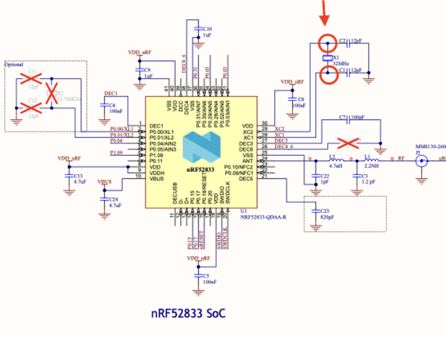
we tried to flash the custom board with the beacon sample here https://developer.nordicsemi.com/nRF_Connect_SDK/doc/latest/zephyr/samples/bluetooth/beacon/README.html

Connect debug out header P19 on DK to jtag-style connector on custom board. Connect custom board to power supply.

Testing as follows:

1.Program the 52833 chip on the dk without the connection above

Result:  success, DK beacons as expected

2.Program the 52833 chip on the dk with the connection above, but do not power the custom board

Result: success, DK beacons as expected. Custom board does not beacon as it is not powered.

3.Program the 52833 chip on the custom board with connection above and power.

Result: DK does not beacon, setup programs custom board only. Successfully program the custom board with no errors in VSCode when connecting or flashing. However, board is till not beaconing at all.

The VS code message for the third test
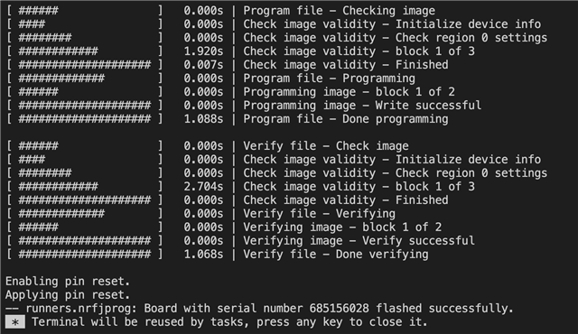
We then examined the voltage of the chip

Following measurements were done:

Measurement

DK Result

Custom Board Result

Voltage at DEC1

1.1 V

0.75V

Voltage at Vbus

0V

< 0.001V

Following these results, capacitor C24 in our custom board was removed. No difference in measure Voltage was observed. Custom board is still not functional.

Question:

1. did we have a correct setup to flash the custom board

2. what could be the reason that Voltage at DEC1 is not correct on our custom board

Thank you for reading through this problem.

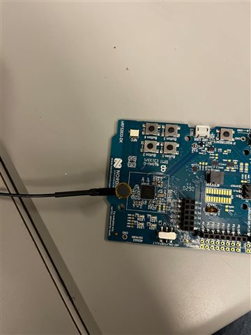
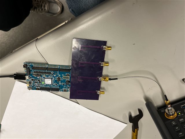
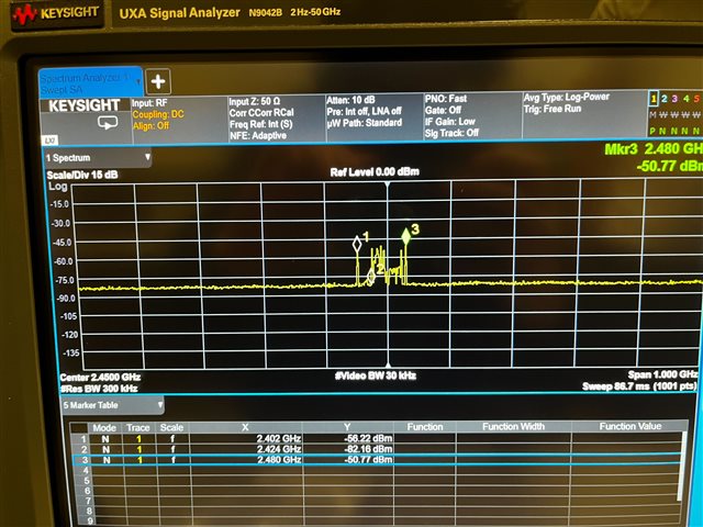
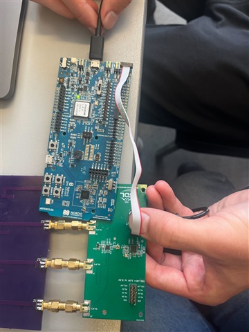
  • We measured the radiated signal using a spectrum analyzer as shown in the setup, and a single antenna tuned for 2.45 GHz (confirmed using VNA).

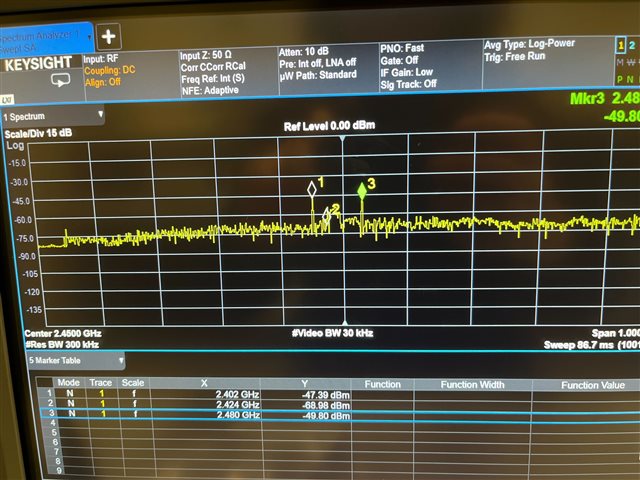
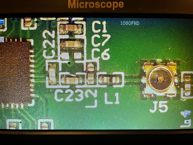
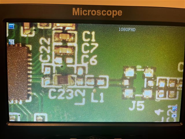
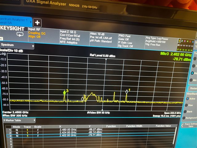
    After a few measurements, the DK was advertising at a power around -47 dBm. See setup and results below. We added a connector to J5, as shown, to disconnect the trace antenna and consider only the radio output. Even with this setup, DK is still beaconing and is visible on the nRF connect mobile application (which shows around -90 dBm).

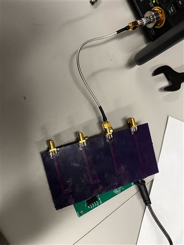
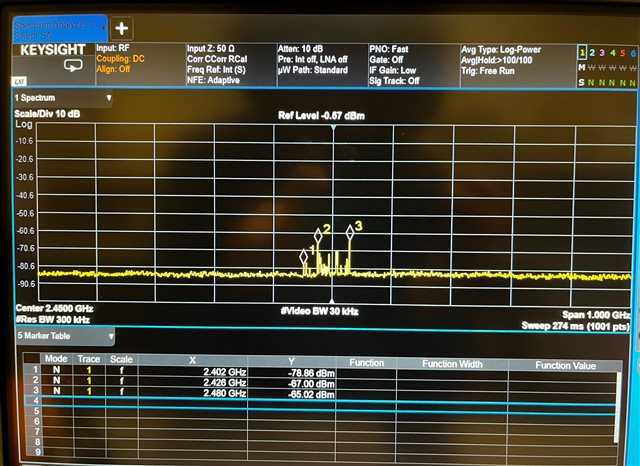
    The custom PCB has a transmit power of around -50 dBm at the BLE advertising channels. See setup and results below; results are similar in terms of signal power on the spectrum analyzer. Note, there is no antenna attached to the custom PCB, this is purely the signal from the radio, not the ant path. 

    Yesterday, when we measured the power from the ant path, the custom PCB showed a magnitude of around -70dB.

  • Hi,

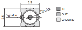
    It seems that you're actually measuring something with the radiated test on the custom board. I therefore find it strange that it's such a difference between the conducted measurements when comparing the DK and the custom board. This might be a longshot, but could you try to rotate the J5 connector? I've seen some cases where the connector has been accidently placed the wrong way resulting in similar conducted measurements. 

    best regards

    Jared 

  • As mentioned in a previous reply, the J5 connector is in the correct orientation (as specified in the datasheet) to measure the point after the matching network on the ant path when the probe is conencted.


  • For clarity, we removed the J5 connector and probed with coax probe at the conductor signal trace (directly at ANT pin) and we are getting simlar results. See setup and results below: 

  • Hello Jared, we are going to replace nRF chipset with new components just to make sure that it is not damaged or does not have any assembly issues.

    Also, can you please review the PCB layout and give your inputs/comments on GND via stitching near  nRF52833 and review  routing/impedance matching of the overall  RF path from nRF source till each of the SMA connectors? 

    Our custom design files are located at http://surl.li/duitk.

    Thanks,

    Nimesh


Related