MCUboot clash with USB Mass Device Littlefs Partition

Hi everyone,

I am trying to run a Zephyr application (NRF52833 device) which has external flash accessed via SPI. On the external flash, there is a second image (MCUboot) and a Littlefs partition.

The Zephyr application is configured to be a USB Mass storage device where the littlefs partition can be accessed either via LittleFS explorer (Windows) or Littlefs_fuse (Linux).

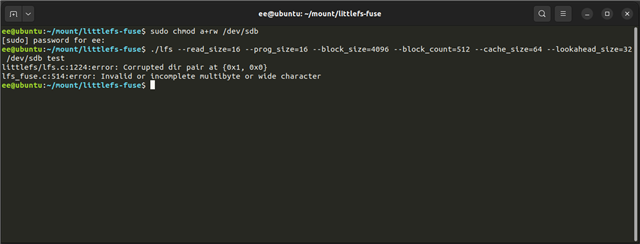
If I have MCUboot disabled, the application works fine and I can access/read/write to the littlefs partition fine in both Windows and Linux. If I enable MCUboot – I cannot access the littlefs partition via USB (see littlefs_fuse screenshot).

I have attached the relevant the .conf files and the .dts file for the nrf52833 board.

MCUBoot.conf

CONFIG_MAIN_STACK_SIZE=10240

CONFIG_DEBUG_OPTIMIZATIONS=y

# Enable flash operations
CONFIG_FLASH=y

# This must be increased to accommodate the bigger images.
CONFIG_BOOT_MAX_IMG_SECTORS=4096

CONFIG_PM_PARTITION_SIZE_MCUBOOT=0x20000

# Disable UART Console and enable the RTT console
CONFIG_UART_CONSOLE=n
CONFIG_RTT_CONSOLE=y
CONFIG_USE_SEGGER_RTT=y

# Config logger
CONFIG_LOG_BACKEND_RTT=y
CONFIG_LOG_BACKEND_UART=n
CONFIG_LOG_MODE_MINIMAL=y
CONFIG_LOG=y
CONFIG_LOG_DEFAULT_LEVEL=0

CONFIG_MULTITHREADING=y

CONFIG_SIZE_OPTIMIZATIONS=y

# MCUBoot serial
CONFIG_MCUBOOT_SERIAL=y
CONFIG_BOOT_SERIAL_CDC_ACM=y
CONFIG_MCUBOOT_INDICATION_LED=y
CONFIG_BOOT_SERIAL_DETECT_DELAY=10

# USB
CONFIG_USB_DEVICE_STACK=y
CONFIG_USB_DEVICE_PRODUCT="MCUBOOT"
CONFIG_USB_CDC_ACM=y
CONFIG_USB_COMPOSITE_DEVICE=n
CONFIG_USB_MASS_STORAGE=n

Proj.conf

CONFIG_CPLUSPLUS=y
CONFIG_NEWLIB_LIBC=y
CONFIG_LIB_CPLUSPLUS=y

CONFIG_SOC_SERIES_NRF52X=y
CONFIG_SOC_NRF52833_QIAA=y

CONFIG_DEBUG_OPTIMIZATIONS=y

CONFIG_RESET_ON_FATAL_ERROR=n

CONFIG_SYSTEM_WORKQUEUE_STACK_SIZE=4096
CONFIG_MAIN_STACK_SIZE=2048 

# Enable MPU
CONFIG_ARM_MPU=y

# Enable hardware stack protection
CONFIG_HW_STACK_PROTECTION=y

# Enable RTT
CONFIG_USE_SEGGER_RTT=y
CONFIG_RTT_CONSOLE=y

# enable GPIO
CONFIG_GPIO=y

# enable uart driver
CONFIG_SERIAL=y

# enable console
CONFIG_CONSOLE=y
CONFIG_UART_CONSOLE=n

# additional board options
CONFIG_GPIO_AS_PINRESET=y

CONFIG_PINCTRL=y
CONFIG_ASSERT=y

CONFIG_LOG=y
CONFIG_LOG_MODE_DEFERRED=y # Using deferred for time being as immediate casues hang due to interaction with shell
CONFIG_LOG_SPEED=y

CONFIG_PRINTK=y 

# K Events
CONFIG_EVENTS=y

# Perpherials 
CONFIG_I2C=y
CONFIG_GPIO=y
CONFIG_SPI=y

# AEM
CONFIG_HEAP_MEM_POOL_SIZE=2048
CONFIG_APP_EVENT_MANAGER=y
CONFIG_APP_EVENT_MANAGER_LOG_LEVEL_OFF=y # Logs disabled unless required for debugging


# CAF
CONFIG_CAF=y

# Buttons
CONFIG_CAF_BUTTON_EVENTS=y
CONFIG_CAF_BUTTONS_LOG_LEVEL_WRN=y

# Click
CONFIG_CAF_CLICK_EVENTS=y
CONFIG_CAF_CLICK_DETECTOR_LOG_LEVEL_WRN=y

#########################

# Debug
CONFIG_THREAD_STACK_INFO=y
CONFIG_KERNEL_SHELL=y
CONFIG_THREAD_MONITOR=y
CONFIG_BOOT_BANNER=n
CONFIG_THREAD_NAME=y
CONFIG_INIT_STACKS=y
CONFIG_POSIX_CLOCK=y
CONFIG_DATE_SHELL=y
CONFIG_STATS=y
CONFIG_THREAD_RUNTIME_STATS=y
CONFIG_THREAD_RUNTIME_STATS_USE_TIMING_FUNCTIONS=y

# Toolchain
CONFIG_NEWLIB_LIBC=y

# Bootloader
CONFIG_BOOTLOADER_MCUBOOT=y

# Shell
CONFIG_SHELL=y
CONFIG_SHELL_CMDS=y
CONFIG_SHELL_LOG_BACKEND=y
CONFIG_SHELL_BACKEND_RTT=y
CONFIG_I2C_SHELL=y
CONFIG_DEVICE_SHELL=y
CONFIG_SHELL_BACKENDS=y
CONFIG_SHELL_GETOPT=y
CONFIG_STATS_SHELL=y
CONFIG_SHELL_CMD_ROOT="login"
CONFIG_SHELL_CMDS_SELECT=y
CONFIG_SHELL_START_OBSCURED=n

# Buttons
CONFIG_CAF_BUTTONS=y
CONFIG_CAF_BUTTONS_DEF_PATH="custom/buttons_def.h"
CONFIG_CAF_BUTTONS_POLARITY_INVERSED=y

# Click
CONFIG_CAF_CLICK_DETECTOR=y
CONFIG_CAF_CLICK_DETECTOR_DEF_PATH="custom/click_detector_def.h"

# USB CDC
CONFIG_STDOUT_CONSOLE=y
CONFIG_USB_DEVICE_STACK=y
CONFIG_USB_DEVICE_PRODUCT="CUSTOM MASS DEVICE"
CONFIG_USB_DRIVER_LOG_LEVEL_ERR=y
CONFIG_USB_DEVICE_LOG_LEVEL_ERR=y
CONFIG_USB_CDC_ACM_LOG_LEVEL_ERR=y
CONFIG_SERIAL=y
CONFIG_UART_INTERRUPT_DRIVEN=y
CONFIG_UART_LINE_CTRL=y
CONFIG_SHELL_BACKEND_SERIAL=y
CONFIG_ISR_STACK_SIZE=4096
CONFIG_USB_NRFX_WORK_QUEUE_STACK_SIZE=2048
CONFIG_LOG_PROCESS_THREAD_STACK_SIZE=4096

## SHELL to Uart interface
CONFIG_SHELL_BACKEND_SERIAL_INIT_PRIORITY=51
CONFIG_SHELL_PROMPT_UART="uart: "

# FLASH Driver
CONFIG_FLASH=y
CONFIG_NORDIC_QSPI_NOR=y

# Setup Little Fs system
CONFIG_SPI_NOR=y
CONFIG_SPI_NOR_FLASH_LAYOUT_PAGE_SIZE=4096  

CONFIG_FLASH_MAP=y
CONFIG_FLASH_PAGE_LAYOUT=y

CONFIG_FILE_SYSTEM=y
CONFIG_FILE_SYSTEM_LITTLEFS=y

CONFIG_FS_LOG_LEVEL_WRN=y

CONFIG_PM_PARTITION_REGION_LITTLEFS_EXTERNAL=y
CONFIG_PM_PARTITION_SIZE_LITTLEFS=0x0200000

# USB Composite device + littleFS MSC Config
CONFIG_USB_COMPOSITE_DEVICE=y
CONFIG_USB_MASS_STORAGE=y
CONFIG_USB_MASS_STORAGE_LOG_LEVEL_ERR=y
CONFIG_USB_DEVICE_INITIALIZE_AT_BOOT=n


CONFIG_DISK_DRIVER_FLASH=y
CONFIG_MASS_STORAGE_DISK_NAME="NAND"

Custom_Board.dts

/dts-v1/;
#include <nordic/nrf52833_qiaa.dtsi>
#include <zephyr/dt-bindings/adc/adc.h>
#include <zephyr/dt-bindings/adc/nrf-adc.h>
#include <zephyr/dt-bindings/led/led.h>
#include "custom-pinctrl.dtsi"

/ {
	model = "Custom Rig";
	compatible = "company,custom";
	zephyr,user {
		io-channels = <&adc 0>, <&adc 1>, <&adc 2>, <&adc 3>, <&adc 4>, <&adc 6>;	
	};

	chosen {
		zephyr,console = &uart1;
		zephyr,shell-uart = &cdc_acm_uart0;
		zephyr,uart-mcumgr = &uart1;
		zephyr,bt-mon-uart = &uart1;
		zephyr,bt-c2h-uart = &uart1;
		zephyr,sram = &sram0;
		zephyr,flash = &flash0;
		zephyr,code-partition = &slot0_partition;
		nordic,pm-ext-flash = &spi_flash0;
	};

	aliases {
		statusled = &left_right_led;
		mcuboot-button0 = &startbutton;
		mcuboot-led0 = &left_right_led;
	};

	
	fstab {
		compatible = "zephyr,fstab";
		lfs1: lfs1 {
			compatible = "zephyr,fstab,littlefs";
			mount-point = "/lfs";
			partition = <&storage>;
			//automount;
			read-size = <16>;
			prog-size = <16>;
			cache-size = <64>;
			lookahead-size = <32>;
			block-cycles = <512>;
		};
	};

	msc_disk0 {
		compatible = "zephyr,flash-disk";
		partition = <&storage>;
		disk-name = "NAND";
		cache-size = <4096>;
	};

	leds {
		compatible = "gpio-leds";
		left_right_led: leftrightled {
			gpios = <&gpio0 31 GPIO_ACTIVE_HIGH>;
			label = "Power LED";
		};
	};
	
	pwm {
		compatible = "pwm-leds";
		pump0: pump_0 {
			pwms = <&pwm0 0 PWM_MSEC(20) PWM_POLARITY_NORMAL>;
		};
	};
	
	buttons {
		compatible = "gpio-keys";
		powerbutton: power_button {
			gpios = <&gpio0 11 (GPIO_PULL_UP | GPIO_ACTIVE_LOW)>;
			label = "Power Button";
		};
		
		leftrightbutton: left_right_button {
			gpios = <&gpio0 30 (GPIO_PULL_UP | GPIO_ACTIVE_LOW)>;
			label = "Left Righ button";
		};
		
		startbutton: start_button {
			gpios = <&gpio1 5 (GPIO_PULL_UP | GPIO_ACTIVE_LOW)>;
			label = "Start Button button";
		};
	};

	
};

&gpiote {
	status = "okay";
};

&gpio0 {
	status = "okay";
};

&gpio1 {
	status = "okay";
};


&spi1 {
	compatible = "nordic,nrf-spi";
	status = "disabled";
};

&spi2 {
	compatible = "nordic,nrf-spi";
	status = "okay";
	cs-gpios = <&gpio0 8 GPIO_ACTIVE_LOW>; // Flash SPI CS pin
	pinctrl-0 = <&spi2_default>;
	pinctrl-1 = <&spi2_sleep>;
	pinctrl-names = "default", "sleep";

	spi_flash0: w25q01jvzeiq@0 {
		compatible = "jedec,spi-nor";
		reg = <0>;
		spi-max-frequency = <133000000>;
		jedec-id = [ef 40 17]; 
		size = <0x4000000>; // 32MBits
		has-dpd; // Device Power Down 
		t-enter-dpd = <3500>;  // used tdp value (page 66) - 3us, used 3.5us for increased time 
		t-exit-dpd = <20000>;  // used tvsl value (page 62) - 20us before first read delay
	};


};


&flash0 {

	partitions {
		compatible = "fixed-partitions";
		#address-cells = <1>;
		#size-cells = <1>;

		boot_partition: partition@0 {
			reg = <0x00000000 0xC000>;
		};
		slot0_partition: partition@c000 {
			reg = <0x0000C000 0x32000>;
		};

		scratch_partition: partition@70000 {
			reg = <0x00070000 0xA000>;
		};
	
		};
	};


 zephyr_udc0: &usbd {
	compatible = "nordic,nrf-usbd";
	status = "okay";

	cdc_acm_uart0: cdc_acm_uart0 {
		compatible = "zephyr,cdc-acm-uart";
	};
}; 

&spi_flash0 {
	partitions {
		compatible = "fixed-partitions";
		#address-cells = <1>;
		#size-cells = <1>;

		slot1_partition: partition@0 {
			reg = <0x00000000 0x60000>;
		};
		
		storage: partition@60000 {
			reg = <0x00060000 0x0200000>;
		};

	};
};


I have also attached the compiled partition.yaml which seems to show all partitions are in the right place.

Partitions.yaml

app:
  address: 0x20200
  end_address: 0x80000
  region: flash_primary
  size: 0x5fe00
external_flash:
  address: 0x260000
  end_address: 0x800000
  region: external_flash
  size: 0x5a0000
littlefs_storage:
  address: 0x60000
  device: DT_CHOSEN(nordic_pm_ext_flash)
  end_address: 0x260000
  placement:
    before:
    - tfm_storage
    - end
  region: external_flash
  size: 0x200000
mcuboot:
  address: 0x0
  end_address: 0x20000
  placement:
    before:
    - mcuboot_primary
  region: flash_primary
  size: 0x20000
mcuboot_pad:
  address: 0x20000
  end_address: 0x20200
  placement:
    before:
    - mcuboot_primary_app
  region: flash_primary
  size: 0x200
mcuboot_primary:
  address: 0x20000
  end_address: 0x80000
  orig_span: &id001
  - mcuboot_pad
  - app
  region: flash_primary
  size: 0x60000
  span: *id001
mcuboot_primary_app:
  address: 0x20200
  end_address: 0x80000
  orig_span: &id002
  - app
  region: flash_primary
  size: 0x5fe00
  span: *id002
mcuboot_secondary:
  address: 0x0
  device: DT_CHOSEN(nordic_pm_ext_flash)
  end_address: 0x60000
  placement:
    align:
      start: 0x4
  region: external_flash
  share_size:
  - mcuboot_primary
  size: 0x60000
sram_primary:
  address: 0x20000000
  end_address: 0x20020000
  region: sram_primary
  size: 0x20000

I must be missing something however I am not sure what direction to proceed in.

I have read that enabling mcuboot ignores the board.dts and uses the partition manager however the partition.yaml suggests this is okay? (maybe not..)

Has anyone come across this before?

Thanks,

David

  • Hi David,


    Can you share the logs of each case?


    Your pm_static.yml will offset your application now, and in the case where mcuboot image is not present; you will never go to your application.


    DEng01 said:
    unable to connect (partition looks corrupted?).

    This is always expected the very first time you boot up with an empty storage area, as it needs to be formatted to littlefs.

    This indicates that you have two different areas where the littlefs_storage is located between the two builds.


    Unmodified output, you can see that it selects 6 pages:

    [00:00:00.000,335] <inf> flashdisk: Initialize device NAND                
    [00:00:00.000,366] <inf> flashdisk: offset e0000, sector size 512, page size 4096, volume size 131072
    Area 6 at 0xf0000 on mx25r6435f@0 for 24576 bytes
    [00:00:00.000,610] <inf> littlefs: LittleFS version 2.5, disk version 2.0
    [00:00:00.000,823] <inf> littlefs: FS at mx25r6435f@0:0xf0000 is 6 0x1000-byte blocks with 512 cycle
    [00:00:00.000,854] <inf> littlefs: sizes: rd 16 ; pr 16 ; ca 64 ; la 32
    [00:00:00.001,281] <err> littlefs: WEST_TOPDIR/modules/fs/littlefs/lfs.c:1234: Corrupted dir pair at {0x0, 0x1}
    [00:00:00.001,281] <wrn> littlefs: can't mount (LFS -84); formatting
    [00:00:00.205,963] <inf> littlefs: /lfs mounted
    

    Removing all Partition Manager and mcuboot configs (ie. using the DTS definition), you can see that it selects 32 pages:

    [00:00:00.405,639] <inf> flashdisk: Initialize device NAND
    [00:00:00.405,639] <inf> flashdisk: offset e0000, sector size 512, page size 4096, volume size 131072
    Area 0 at 0xe0000 on mx25r6435f@0 for 131072 bytes
    [00:00:00.405,914] <inf> littlefs: LittleFS version 2.5, disk version 2.0
    [00:00:00.406,158] <inf> littlefs: FS at mx25r6435f@0:0xe0000 is 32 0x1000-byte blocks with 512 cycle
    [00:00:00.406,188] <inf> littlefs: sizes: rd 16 ; pr 16 ; ca 64 ; la 32
    [00:00:00.406,616] <err> littlefs: WEST_TOPDIR/modules/fs/littlefs/lfs.c:1234: Corrupted dir pair at {0x0, 0x1}
    [00:00:00.406,616] <wrn> littlefs: can't mount (LFS -84); formatting
    [00:00:00.611,297] <inf> littlefs: /lfs mounted


    If you go back-and-forth between these two builds, it will continue to format your littlefs area(s).


    Kind regards,

    Håkon

  • Hi Håkon, 

    you have raised some very good points.

    I have looked at the log for the build with MUBoot and I have noticed that flashdisk: offset e0000 and FS at mx25r6435f@0:0xf0000 . I thought maybe there was an address mismatch causing the littlefs_fuse to fail. 

    I modified the following:

    storage_partition: partition@f0000 {
    			label = "lfs_storage";
    			reg = <0x000f0000 0x00020000>;
    		};

    The device still cannot connect to littlefs_fuse.

    Here are the logs:

    00> *** Booting Zephyr OS build v3.2.99-ncs1 ***
    
    00> [00:00:00.000,335] <inf> flashdisk: Initialize device NAND
    
    00> [00:00:00.000,335] <inf> flashdisk: offset f0000, sector size 512, page size 4096, volume size 131072
    
    00> Area 6 at 0xf0000 on mx25r6435f@0 for 24576 bytes
    
    00> [00:00:00.000,488] <inf> littlefs: LittleFS version 2.5, disk version 2.0
    
    00> [00:00:00.000,732] <inf> littlefs: FS at mx25r6435f@0:0xf0000 is 6 0x1000-byte blocks with 512 cycle
    
    00> [00:00:00.000,732] <inf> littlefs: sizes: rd 16 ; pr 16 ; ca 64 ; la 32
    
    00> [00:00:00.001,281] <inf> littlefs: /lfs mounted
    
    00> Mount /lfs: 0
    
    00> /lfs: bsize = 16 ; frsize = 4096 ; blocks = 6 ; bfree = 4
    
    00> /lfs opendir: 0
    
    00> End of files
    
    00> [00:00:00.053,039] <inf> main: The device is put in USB mass storage mode.

    I have tried plugging and unplugging the device to make sure the machine enumerated with the nrf52 device with fs already formatted to no success.

    Do you have any more suggestions that I could try?

    Have you tried littlefs_fuse on your end?

    Thanks,

    David

  • Hi,


    My apologies for misunderstanding the scenario.

    I think I have replicated the issue and found the source.

    I have moved both DTS and PM declared partitions to match, and found that when not using mcuboot, this is the device that the flash disk subsys picks up this "dev":

    (gdb) print flash_disks.info
    $2 = {node = {{head = 0x20000dc4 <disk_access_list>, next = 0x20000dc4 <disk_access_list>}, {
          tail = 0x20000dc4 <disk_access_list>, prev = 0x20000dc4 <disk_access_list>}}, name = 0x22f59 "NAND", 
      ops = 0x22680 <flash_disk_ops>, dev = 0x221c8 <__device_dts_ord_12>}


    While this is the "dev" that is picked up when using multi-image build:

    (gdb) print flash_disks.info
    $1 = {node = {{head = 0x20000dc4 <disk_access_list>, next = 0x20000dc4 <disk_access_list>}, {
          tail = 0x20000dc4 <disk_access_list>, prev = 0x20000dc4 <disk_access_list>}}, name = 0x22f59 "NAND", 
      ops = 0x22680 <flash_disk_ops>, dev = 0x221b4 <__device_dts_ord_125>}


    When we look at the very top of build-folder/zephyr/include/generated/devicetree_generated.h, we can see the device table:

     * Node dependency ordering (ordinal and path):
     *   0   /
     *   1   /aliases
     *   2   /analog-connector
     *   3   /chosen
     *   4   /connector
     *   5   /entropy_bt_hci
     *   6   /soc
     *   7   /pin-controller
     *   8   /pin-controller/qspi_default
     *   9   /pin-controller/qspi_sleep
     *   10  /soc/interrupt-controller@e000e100
     *   11  /soc/qspi@40029000
     *   12  /soc/qspi@40029000/mx25r6435f@0
     *   13  /soc/qspi@40029000/mx25r6435f@0/partitions
     *   14  /soc/qspi@40029000/mx25r6435f@0/partitions/partition@0
     *   15  /msc_disk0
     *   16  /soc/timer@4000a000
     *   17  /sw-pwm
     *   18  /buttons
     *   19  /soc/gpio@50000000
     *   20  /buttons/button_0
     *   21  /buttons/button_1
     *   22  /buttons/button_2
     *   23  /buttons/button_3
     *   24  /cpus
     *   25  /cpus/cpu@0
     *   26  /cpus/cpu@0/itm@e0000000
     *   27  /leds
     *   28  /leds/led_0
     *   29  /leds/led_1
     *   30  /leds/led_2
     *   31  /leds/led_3
     *   32  /pin-controller/i2c0_default
     *   33  /pin-controller/i2c0_default/group1
     *   34  /pin-controller/i2c0_sleep
     *   35  /pin-controller/i2c0_sleep/group1
     *   36  /pin-controller/i2c1_default
     *   37  /pin-controller/i2c1_default/group1
     *   38  /pin-controller/i2c1_sleep
     *   39  /pin-controller/i2c1_sleep/group1
     *   40  /pin-controller/pwm0_default
     *   41  /pin-controller/pwm0_default/group1
     *   42  /pin-controller/pwm0_sleep
     *   43  /pin-controller/pwm0_sleep/group1
     *   44  /pin-controller/qspi_default/group1
     *   45  /pin-controller/qspi_sleep/group1
     *   46  /pin-controller/qspi_sleep/group2
     *   47  /pin-controller/spi0_default
     *   48  /pin-controller/spi0_default/group1
     *   49  /pin-controller/spi0_sleep
     *   50  /pin-controller/spi0_sleep/group1
     *   51  /pin-controller/spi1_default
     *   52  /pin-controller/spi1_default/group1
     *   53  /pin-controller/spi1_sleep
     *   54  /pin-controller/spi1_sleep/group1
     *   55  /pin-controller/spi2_default
     *   56  /pin-controller/spi2_default/group1
     *   57  /pin-controller/spi2_sleep
     *   58  /pin-controller/spi2_sleep/group1
     *   59  /pin-controller/spi3_default
     *   60  /pin-controller/spi3_default/group1
     *   61  /pin-controller/spi3_sleep
     *   62  /pin-controller/spi3_sleep/group1
     *   63  /pin-controller/uart0_default
     *   64  /pin-controller/uart0_default/group1
     *   65  /pin-controller/uart0_default/group2
     *   66  /pin-controller/uart0_sleep
     *   67  /pin-controller/uart0_sleep/group1
     *   68  /pin-controller/uart1_default
     *   69  /pin-controller/uart1_default/group1
     *   70  /pin-controller/uart1_default/group2
     *   71  /pin-controller/uart1_sleep
     *   72  /pin-controller/uart1_sleep/group1
     *   73  /pwmleds
     *   74  /soc/pwm@4001c000
     *   75  /pwmleds/pwm_led_0
     *   76  /soc/acl@4001e000
     *   77  /soc/adc@40007000
     *   78  /soc/ccm@4000f000
     *   79  /soc/clock@40000000
     *   80  /soc/comparator@40013000
     *   81  /soc/ecb@4000e000
     *   82  /soc/egu@40014000
     *   83  /soc/egu@40015000
     *   84  /soc/egu@40016000
     *   85  /soc/egu@40017000
     *   86  /soc/egu@40018000
     *   87  /soc/egu@40019000
     *   88  /soc/ficr@10000000
     *   89  /soc/gpiote@40006000
     *   90  /soc/i2c@40003000
     *   91  /soc/i2c@40004000
     *   92  /soc/i2s@40025000
     *   93  /soc/memory@20000000
     *   94  /soc/mwu@40020000
     *   95  /soc/nfct@40005000
     *   96  /soc/pdm@4001d000
     *   97  /soc/power@40000000
     *   98  /soc/ppi@4001f000
     *   99  /soc/pwm@40021000
     *   100 /soc/pwm@40022000
     *   101 /soc/pwm@4002d000
     *   102 /soc/qdec@40012000
     *   103 /soc/random@4000d000
     *   104 /soc/rtc@4000b000
     *   105 /soc/rtc@40011000
     *   106 /soc/rtc@40024000
     *   107 /soc/spi@40003000
     *   108 /soc/spi@40004000
     *   109 /soc/spi@40023000
     *   110 /soc/gpio@50000300
     *   111 /soc/spi@4002f000
     *   112 /soc/temp@4000c000
     *   113 /soc/timer@40008000
     *   114 /soc/timer@40009000
     *   115 /soc/timer@4001a000
     *   116 /soc/timer@4001b000
     *   117 /soc/timer@e000e010
     *   118 /soc/uart@40002000
     *   119 /soc/uart@40028000
     *   120 /soc/uicr@10001000
     *   121 /soc/usbd@40027000
     *   122 /soc/watchdog@40010000
     *   123 /soc/crypto@5002a000
     *   124 /soc/crypto@5002a000/crypto@5002b000
     *   125 /soc/flash-controller@4001e000
     *   126 /soc/flash-controller@4001e000/flash@0
     *   127 /soc/flash-controller@4001e000/flash@0/partitions
     *   128 /soc/flash-controller@4001e000/flash@0/partitions/partition@0
     *   129 /soc/flash-controller@4001e000/flash@0/partitions/partition@c000
     *   130 /soc/flash-controller@4001e000/flash@0/partitions/partition@73000
     *   131 /soc/flash-controller@4001e000/flash@0/partitions/partition@da000
     *   132 /soc/radio@40001000
     *   133 /soc/radio@40001000/ieee802154
     *
     * Definitions derived from these nodes in dependency order are next,
     * followed by /chosen nodes.
     */


    We are interested in these two:

    12  /soc/qspi@40029000/mx25r6435f@0
    ...
    125 /soc/flash-controller@4001e000


    Now we can clearly see that the multi-image build selects the wrong device when trying to lookup the disk flash meta data, thus explaning why lfs does not work in combination with USB mass storage.


    How to work around this issue:

    By setting the settings partition at offset 0, this now seems to be picked up properly by the build system.

    Here's your project, with modifications:

    4666.mass_nrf52840_offset_0.zip


    Could you try this and see if it now works on your side as well?

    I ran:

    sudo ./lfs --read_size=16 --prog_size=16 --block_size=4096 --block_count=32 --cache_size=64 --lookahead_size=32 /dev/sdX mount/
    sudo touch mount/test
     

    Here's the output after I un-mounted the FS on my PC and rebooted the nRF:

    *** Booting Zephyr OS build v3.2.99-ncs2 ***
    *** Booting Zephyr OS build v3.2.99-ncs2 ***
    [00:00:00.000,335] <inf> flashdisk: Initialize device NAND
    [00:00:00.000,366] <inf> flashdisk: offset 0, sector size 512, page size 4096, volume size 131072
    Area 0 at 0x0 on mx25r6435f@0 for 131072 bytes
    [00:00:00.000,640] <inf> littlefs: LittleFS version 2.5, disk version 2.0
    [00:00:00.000,701] <inf> littlefs: FS at mx25r6435f@0:0x0 is 32 0x1000-byte blocks with 512 cycle
    [00:00:00.000,701] <inf> littlefs: sizes: rd 16 ; pr 16 ; ca 64 ; la 32
    [00:00:00.002,044] <inf> littlefs: /lfs mounted
    Mount /lfs: 0
    /lfs: bsize = 16 ; frsize = 4096 ; blocks = 32 ; bfree = 30
    /lfs opendir: 0
      F 0 test
    End of files
    [00:00:00.054,962] <inf> main: The device is put in USB mass storage mode.


    Kind regards,

    Håkon

  • Hi Håkon, 

    That has fixed it! Thank you very much!  While the work around is okay for the time being - I think a ticket should be raised against the bug in multi-image builds. How do you go about doing this? Or have you raised an internal ticket?

    Where can I find the flash_disks file? I cannot seem to find it in the build folder.

    How did you know to look for this when debugging - I have tried looking in here https://developer.nordicsemi.com/nRF_Connect_SDK/doc/latest/zephyr/index.html

    But I can't seem to find the information.

    Thanks for all your help and support.

    David

Related