Xiao BLE Sense Zephyr SD Access Through Expansion Board

Hello All,

I have been trying to get the Xiao BLE Sense with the nrf52840 chip in conjunction with the expansion board to access the SD card using the FatFS example from zephyr. All my processes and files where I got my information will be linked at bottom with references during explanation.

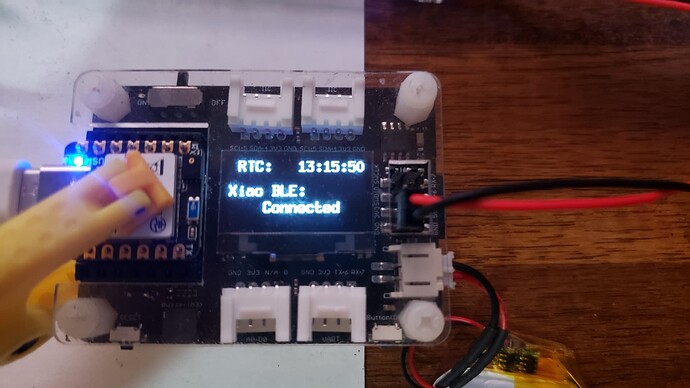
1. I know that the Xiao BLE Sense (1) does not have inherent capabilities with SD card access, to do this I am using the xiao expansion board (2) this uses a micro SD card so I do not know if that interferes with capabilities

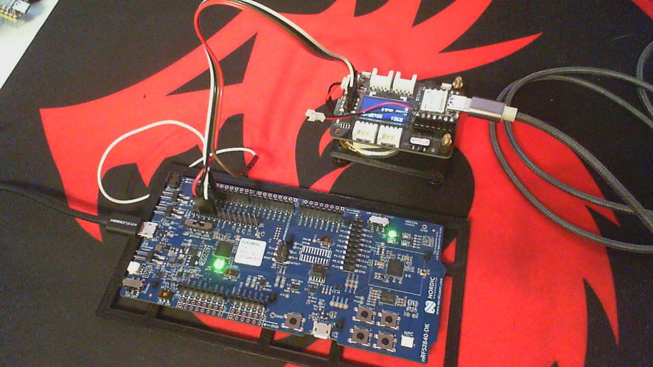
2. I downloaded the FatFS sample from the zephyr GitHub after following the setup guide for zephyr on my machine (3)

3. Within the example and on the read me there is no inherent support for the Xiao BLE Sense or the expansion board from what I saw, so I made the decision that an overlay is in order. Below is the overlay I made and some explanations for decisions I made and things I have tested

&spi2 {
    status = "okay";
    cs-gpios = <&gpio0 0x1c GPIO_ACTIVE_LOW>;
    pinctrl-0=<&spi2_default>;
    pinctrl-1=<&spi2_sleep>;
    pinctrl-names="default", "sleep";
    sdhc0: sdhc@0 {
            compatible = "zephyr,sdhc-spi-slot";
            reg = <0>;
            status = "okay";
            mmc {
                compatible = "zephyr,sdmmc-disk";
                status = "okay";
            };
            spi-max-frequency = <24000000>;
    };
};

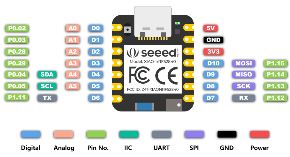
Within this code there are things to point out that I have tested and have found no luck with. After reviewing the schematics of both the Xiao BLE Sense and the expansion board, I found that the mosi miso and sck pins are 15,14,13 respectively, so I felt the need to not change them as those are the pin descriptions from the actual chip (4), which match up to the pin ctrl for the Xiao BLE sense. Within this document as well I see that there is a pin called P0.28_AIN4_LOW_A2_D2 which has the description of d2 at the end. Logically I went to the expansion board schematic (5) (within this schematic it also states the PIN numbers 8.9.10 as mosi miso and sck pins and tried those as well and nothing landed) and found that this had the same ending as the start of the D2_SD_CS which I assume is the chip select pin for the SD card through the expansion board with the corresponding PIN number of 28. which is identified as p0.28 or 0x1c.

here is the prj.conf file as well.

CONFIG_DISK_ACCESS=y
CONFIG_LOG=y
CONFIG_FILE_SYSTEM=y
CONFIG_FAT_FILESYSTEM_ELM=y
CONFIG_PRINTK=y
CONFIG_MAIN_STACK_SIZE=2048
CONFIG_SPI=y
CONFIG_DISK_DRIVER_SDMMC=y

I have not been able to get this working and the errors I get are the SD card storage init error and failure to mount the file system.

if anyone has any insight as to what the error I have made may be I would greatly appreciate it.

Thanks.

References:

1. https://wiki.seeedstudio.com/XIAO_BLE

2. https://wiki.seeedstudio.com/Seeeduino-XIAO-Expansion-Board/

3. https://github.com/zephyrproject-rtos/zephyr/tree/main/samples/subsys/fs/fat_fs

4. https://files.seeedstudio.com/wiki/XIAO-BLE/Seeed-Studio-XIAO-nRF52840-Sense-v1.1.pdf

5. https://files.seeedstudio.com/wiki/Seeeduino-XIAO-Expansion-Board/document/Seeeduino%20XIAO%20Expansion%20board_v1.0_SCH_200824.pdf

  • Hi,

    Could you share how you got it working? I am facing the same issue and I am bit stuck in here. 

    Thank you!

  • Hi,


    If you have an issue, I would recommend that you open a new thread specific to the problem that you're seeing. Remember to share logs and details on what you're observing.


    Kind regards,

    Håkon

  • Hi there,

    So I recently started on the NRF_SDK path and i had the same thought of an Overlay ? or DTS file for the Hardware description based off of the schematic. I have a self test Drag&Drop Uf2 file and the ino file for it on the seeed forum. I lights the LEDs,Test the Flash , Tests the SD card (for a fatfs formatted sd card inserted), displays the results on the OLED I2C display , the buzzer is A3 plays a sound. I did find while testing , sometimes it was better to use the GPIO pin numbers in the sketches to get some to work. the self Test also spits out the Device number , MAC address and sets up a BLE central for LED control.Here is the link to the posts if it's allowed

     I want to start making the same test for it using the NRF_SDK so I'm just beginning.

    I have an nRF52840DK and a Nordic Dongle, and the Xiao SWD expansion board and connect them together here use the JLink with the SDK and Nrf_for Desktop Programmer no problem. Built the blinky and sent to both devices.

    The SD is SPI interface and the CS D2 or GPIO P0.28

    The serial output looks like this.:

    Power ON 


    Xiao Expansion board and MCU check & Test compiled on Aug 13 2024 at 00:45:24
    
    Processor came out of reset.


    Selected MCU: nRF52840


    Xiao Unit: 0993
    
    Playing startup sound
    
    RTC Date & Time is:8/7/24 12:50:34
    
    Testing R G B LED - RED, GREEN, BLUE... 


    Initializing SD card...Card Mounted
    
    Card type: SDHC
    
    Volume type is:    FAT32
    
    SD Volume size (Gb):  29.12
    
    Read I2C 
    
        SDA pin: 4
    
        SCL pin: 5
    
        I2C address: 68


    Xiao MAC: 93:8E:19:D7:65:53


    Advertising Bluetooth Device
    
      as: Xiao 0993

    ---END---

    I find this image to be the most accurate, Good Pinout

    here is a link to the video

    https://forum.seeedstudio.com/t/xiao-expansion-board-drag-drop-testing-uf2-flash-files/275874/4?u=pj_glasso

    is it an overlay that is needed, when is it an Overlay and when is it a Device tree? 

    I get a device tree for the sense version would be different from the BLE only version. (no IMU or PDM mic)

    HTH

    GL Relaxed PJ V

    would a different Overlay be used for this expansion base as well?

    small expansion base with optional flash chip

    Breakable expansion with Flash on bottom

Related