This post is older than 2 years and might not be relevant anymore
More Info: Consider searching for newer posts
This discussion has been locked.
You can no longer post new replies to this discussion. If you have a question you can start a new discussion

Programming Raytac MDBT40 (nRF51822 based) for LED blinking

Dear Nordic family,

I tried programming Raytac MDBT40 with the LED blinking code (taken from the example project of SDK 8) which worked with nRF51822 Bluetooth Low Energy BLE 4 and 2.4GHz Wireless Communication Module (purchased from exploreembedded).

Its getting programmed, but the LED is not blinking.

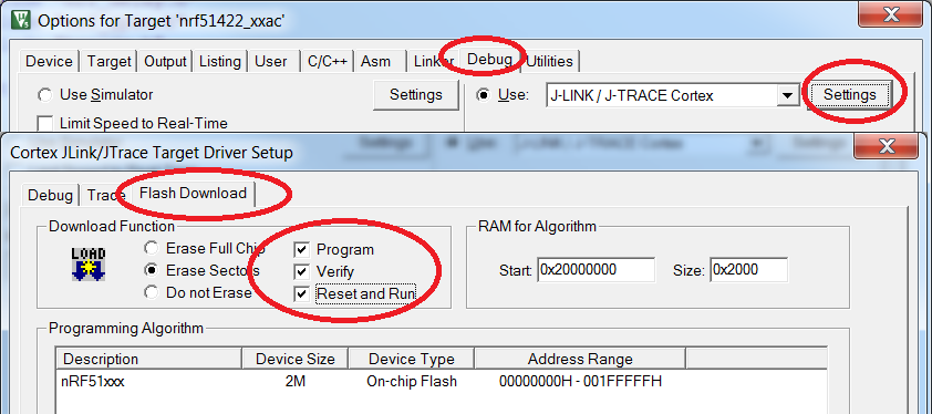
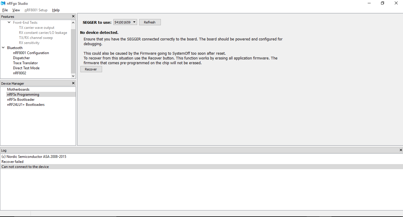
It there any extra software or hardware settings required for programming MDBT40?

Relevant post

  • Hi.

    Is this the example you are using: Blinky Example?

    Are you able to verify the code on the chip using nRFgo Studio?

    Are you sure that you have connected the LED to the correct pin?

    • The Blinky Example you are referring to you is from SDK9. I am trying the equivalent one from SDK8. Functionality is the same. It blinks the LEDs defined in the LEDS_LIST
    • Haven't tried nRFgo Studio.
    • I have connected to pin 0.21 (found from schematics of Raytac) (I assume that's the pin 21 mentioned in the file given inside PCA1000 board file)
  • What board file are you using exactly? What board have you defined in "Target Options->C/C++->Define"?

    Are you using the "blank" example version or the "S110" version?

    Are you able to try to use nRFgo Studio?

  • Hi,

    1. We have made our own board with LEDs connected to pin 21, 22 compatible with board PCA 10028 (In the previous post, I had mentioned it as 10000 by mistake)
    2. Target Options->C/C++->Define: BSP_DEFINES_ONLY BOARD_PCA10028 NRF51
    3. I used blank and s110 version
    4. No. nRFgo Studio is not detecting the device Screenshot of nRFGo main window, showing device not deteced.

    Using, J-lite, at least the device is getting detected and getting erased

    1. What's the difference between the examples in 'blank' and 's110'?
  • The blank example puts your example at IROM1 address 0x00000 and the S110 example expect a S110 softdevice to be present on the IC and puts your example at IROM1 address 0x18000. See this and this thread. This is very important. BLE examples without a Softdevice present on the chip will program to your board without errors, but will not work.

    What does your Flash Download settings look like? It should look like this:

    image description

    My nRFgo Studio looks like that when the J-Link Lite is not correctly connected to the chip. If I make sure the chip is there and has power I can hit "Recover" and it works.

Related