Sleep modes (System ON) example for nRF52833 with nRF Connect SDK 2.3.0

Dear Support Team,

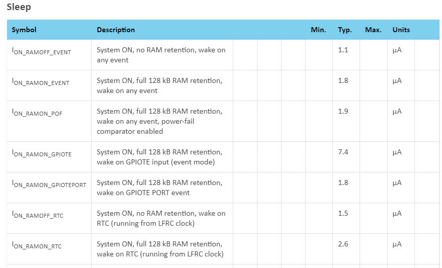
I recently started evaluating a nRF52833 DK board with the nRF Connect SDK 2.3.0. Could you please point me to a working example demonstrating how to configure and use the different sleep modes? I'm interested in the implementation of the various System ON modes described in the data sheet:

Thank you very much in advance and all the best,

Viktor

  • Hi,

    Most nRF Connect SDK examples will enter system on Idle with full RAM retention and one RTC by default when in idle. You will need to disable logging first though, as if not the UART will be active, causing a high current consumption. For the majority of applications this is the sensible idle mode, and you will always need to keep the RTC active.

    There are no examples that demonstrate the different RAM retention levels. However, if you want to, you can take a simple example (like hello world), disable logging, and change the linker configuration to use less RAM and update the RAM power control registers as explained in the product specification. There is no example for that either, but there is a related example demonstrating how to set up RAM retention in system OFF mode in the nRF5x System Off demo you can use as a reference.

  • Hi Einar!

    Thank you for the answer!

    After disabling UART I see consumption corresponding to ON_RAMON_GPIOTE. (7.3uA)

    My question would be how to configure the first 2 sleep modes: ON_RAMOFF_EVENT and ON_RAMON_EVENT.

    The goal that I would like to reach is to find the lowest energy mode which has a short latency when switching to ACTIVE mode again. It can with or without RAM retention. The only only important parameters are:

    - low latency (below 100 ms)

    - low current

    - RTC running

    - GPIO interrupt handling active

    Thank you in advance,

    Viktor

  • Hi Victor,

    I do not have any examples on ON_RAMOFF_EVENT, other than referring to how you can configure the RAM retention at register level as done in the nRF5x System Off demo. I think that has very few practical applications though, and I do not recall seeing system ON sleep with no ram retention ever used. If you have no RAM retention, all initialization will have to happen again when you wake up from sleep, which will will require significant amount of CPU time and resources. So this will likely increase your products average power consumption, which in the end is what matters for battery life.

    Regarding ON_RAMON_EVENT this is also mostly of theoretical use, as it includes the CPU configured to wake up on any event, but no wake-up sources (like RTC, LPCOMP, GPIO,..) actually configured.

    The most relevant sleep mode is systen on sleep mode with RTC, with RAM retention, which is what is used for I_ON_RAMON_RTC (2.6 uA). With this, the RTC keeps running and is used as wakeup source. Also, the full RAM is retained, so you do not need to re-initialize anything. For GPIO, you can use port event instead of in event, and that will give you a lower sleep current consumption, as you see in the table (I_RAMON_GPIOTE_PORT). Combining GPIO port event and RTC and full RAM retention, you should expect to see an idle current consumption of slightly above 3 uA.

    If you find you don't use the full RAM, you can change the linker memory configuration so that the upper part is not used, and disable that in the power register (see how that is done in zephyr/samples/boards/nrf/system_off/src/retained.c). As you see in the table, the difference between full ram retention and no RAM retention is 0.7 uA, so  depending on how much RAM you can live without, this will not make a huge saving, though.

    Einar

  • Hi Einar,

    Thank you for the guidance, now I managed to achieve ~3uA with full RAM retention! I will just sum up here the steps that were needed to get there:

    1, disable logging in the prj.conf file:

    CONFIG_LOG=n
    CONFIG_SERIAL=n

    2, configuring gpio port event:

    Interrupt configuration must be done with GPIO_INT_LEVEL_* flags instead of the GPIO_INT_EDGE_* flags. This was not trivial to find out...

    #define IRQ_ACC_NODE	DT_ALIAS(accirq0)
    const struct gpio_dt_spec sIRQ_pin = GPIO_DT_SPEC_GET_OR(IRQ_ACC_NODE, gpios, {0});
    
    // configuring interrupt
    gpio_pin_configure_dt(&sIRQ_pin, GPIO_INPUT);
    gpio_pin_interrupt_configure_dt(&sIRQ_pin, GPIO_INT_LEVEL_ACTIVE);

    All the best,

    Viktor

  • Actually, it doesn't seem to work fine... there is a very strange behaviour of the development kit, for which I will create a ticket soon and won't detail it here. The main thing is that after repowering the kit from a working state, it doesn't work anymore!

    The code hangs at this call without return error, just running on full gas continuously:

    gpio_pin_interrupt_configure_dt(&sIRQ_pin, GPIO_INT_LEVEL_ACTIVE);

    This only happens when the pin is about to be configured in port event mode, when EDGE flags are chosen there is no issue.

    Is there any project config that I'm missing here?

    Thank you in advance,

    Viktor

Related