

There are different ways of measuring the current consumed by the nRF9160 SIP. Using a dedicated power analyzer is usually the preferred way, as it is often able to accurately measure and plot current draws with a large dynamic range, because of automatic range switching, and with a good time resolution. There are also other possibilities like using an ampere meter or an oscilloscope, but there are limitations to these methods. An ampere meter will only give you the average instantaneous current and further investigation of the current profile is not possible. An oscilloscope on the other hand will give you the opportunity to measure both average current over a given time interval as well as capture the current profile of the LTE event, but the disadvantage of using an oscilloscope is that the dynamic range is fixed, as opposed to a power analyzer which changes the dynamic range based on the current load. Having a current consumption ranging from about 1 uA up to 500 mA on the nRF91, makes it impossible to measure the lowest idle current accurately and at the same time being able to capture the highest peaks, if the dynamic range is fixed.
The Power Profiler Kit II (PPK2) provided by Nordic is a power analyzer that can be used both in ampere meter mode and in SMU (source measure unit) mode. It has automatic dynamic range switching and comes with software that enables you to plot the current consumption over a longer time period.
Measuring current on the nRF9160 DK
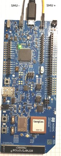
SMU mode
The best way to measure current on the nRF9160 DK is to use a dedicated power analyzer which can provide power and measure current at the same time. For instance the PPK2. This way you can also adjust the voltage to your requirements.
Apply voltage directly on the “nRF current measurement” header, and use the GND terminal on the “External supply” header. Then, adjust the output voltage of your SMU to match the operating conditions of the nRF91 (3.0V – 5.5V).
Note that the USB cable is left plugged in to the DK. This is because all the other components on the DK, e.g. the debugger, need power as well. So everything on the DK except the nRF9160 SIP itself is powered through the USB.
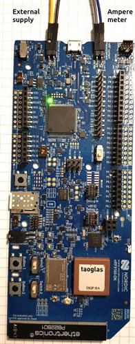
Ampere meter mode
Alternatively you can use the onboard power supply, or a separate power supply on the “External supply” header, and then measure the current flowing through the “nRF current measurement” header, using and ampere meter or similar.
When using the onboard power supply, the current consumption might increase about 10 uA because of noise from the supply and USB cable. It is therefore recommended to leave the USB unconnected and power the DK from an external supply.
 |
 |
| SMU mode | Ampere meter mode |
Checking your measurement setup
It’s a good idea do a sanity check on your measurement setup using a firmware with a known current consumption to see if you have any leakage currents, or if your measurement equipment is accurate enough.
Below is a code snippet which shuts down the modem and puts the chip to system OFF mode.
#include <modem/lte_lc.h>
void main(void)
{
 lte_lc_power_off();
 k_sleep(K_MSEC(1000));
 NRF_REGULATORS->SYSTEMOFF = 1;
}
Here is a precompiled hex file you can flash directly if you quickly want to measure the system OFF current:
Then you can check if it matches the system OFF current in the product specification
Refresh mode
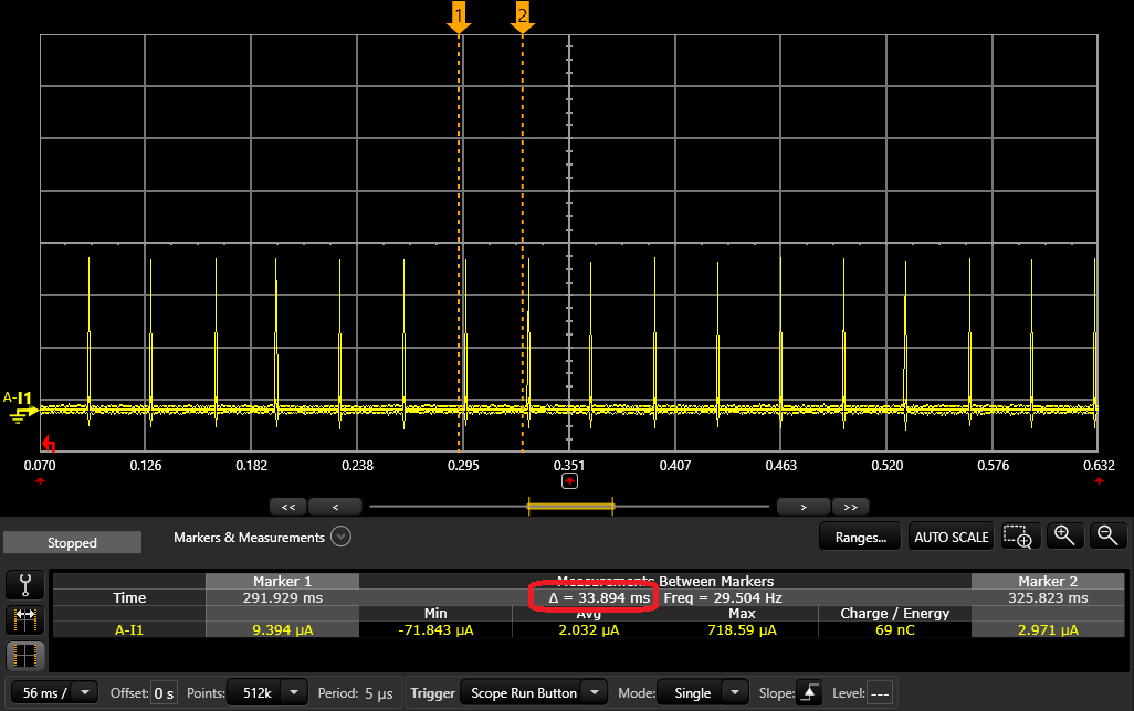
When the internal current load is low (i.e. system ON idle and system OFF) the internal regulator operates in refresh mode, also known as burst mode. In this mode the regulator charges the output capacitor and switches off. Then, when the output voltage (voltage over the capacitor) drops to a certain point, the regulator switches on again and charges up the capacitor. You can see this as regular current spikes drawn from the VDD input. The shorter the interval between the spikes the higher the current draw.
Below is an image of the nRF9160 in system ON idle mode with the RTC running, which is the most common idle mode. You can see that the burst period is about 35 ms, which is normal for this type of idle. In system OFF the period will be closer to 50 ms.
The floor current between the spikes should be very low, typically below 1 uA.
Burst interval:
Floor current:
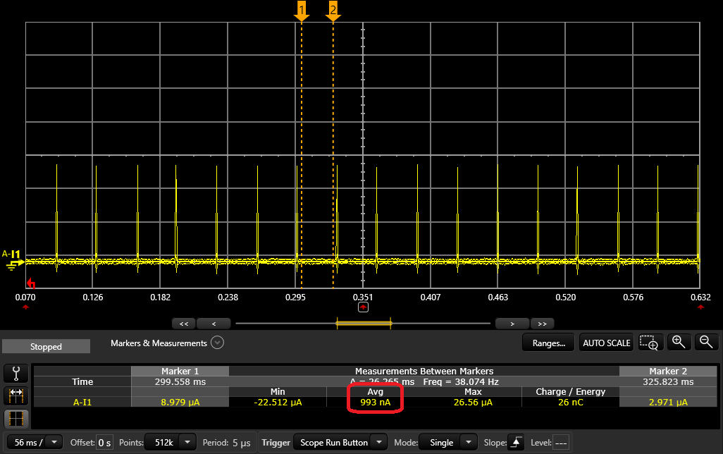
This information can be used to debug some idle current issues. If you have a leakage directly on VDD, caused by other components on the board, you will see that the floor current increases, while the refresh mode burst frequency remains the same. If the increased idle current is caused by the nRF9160 the floor current will most likely remain the same, but the burst frequency will increase.
Measuring current on the UDP sample in NCS
The UDP sample in the nRF Connect SDK (NCS) is power optimized and ideal for doing initial current measurements.
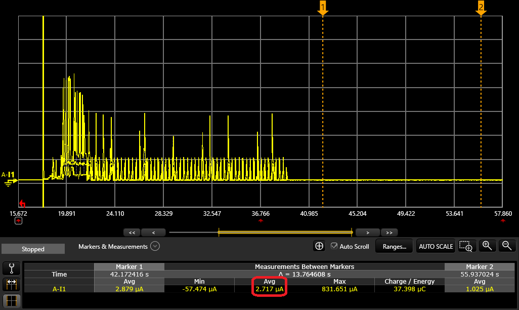
It sets up a UDP socket to a server and transfers a specified amout of data in a specified interval. It is automatically configured to enter PSM mode (if the network supports it) and turns off UART and the logging module to achieve the lowest possible PSM current of 2.7uA. Then it wakes up only to transmitt the UDP data, and goes back to PSM.
PSM and eDRX settings can be configured throught the prj.conf file in the project folder.
Below is a current plot showing the application without any modifications. The area between the cursors is when the modem has entered PSM.
Check if you have actually entered PSM
Sometimes the network will not give you the same parameters as requested. If you are not sure whether or not PSM was enabled you can enable logging in the UDP application. Change the CONFIG_SERIAL=n to =y in the prj.conf file in the project folder.
Look for this line in the log output:
PSM parameter update: TAU: 3600, Active time: 0
If TAU is set to -1, PSM is not supported, otherwise it will show you the PSM interval in seconds.
Using AT commands
If you are using an application where you are controlling the modem with AT commands, for instance the Serial LTE Modem application, you can use AT commands to check the network PSM status.
PSM is requested with the AT+CPSMS set command, however the AT+CPSMS read command will only read back the requested value, not provide any information whether PSM was granted by the network or not.
Use the AT+CEREG? command to read back the PSM settings (<Active-Time> and <Periodic-TAU>). First you will have to set the notification level to 5.
AT+CEREG=5
AT+CEREG?
Sim card current consumption
Usually, if the modem is not in PSM mode, the SIM card is powered on and is in a state called "clock stop mode". It basically means that the SIM is in its lowest power mode, without being shut down completely (as in cutting the power to the SIM). In clock stop mode the SIM consumes somewhere between 0 and 100 uA. 100 uA is specified as the maximum allowed by the 3GPP specification.
The SIM card is powered by the SIM_1V8 pin on the nRF91 which means that the SIM power consumption is directly reflected on the nrF9160 VDD input, scaled by the SIM_1V8/VDD voltage ratio.
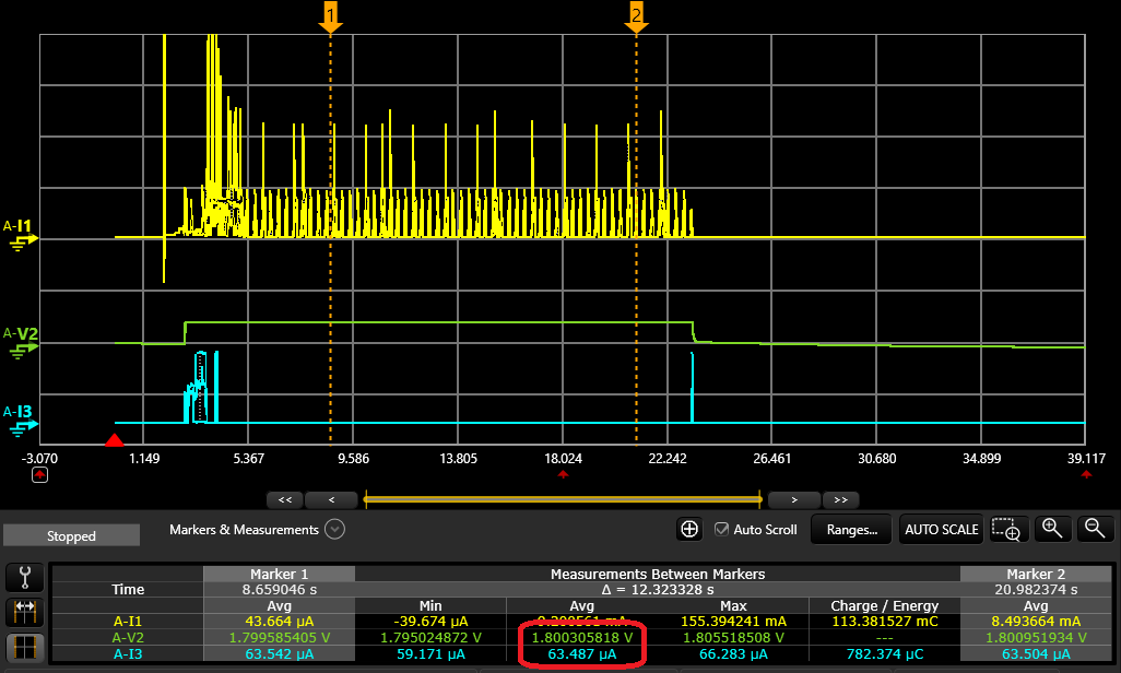
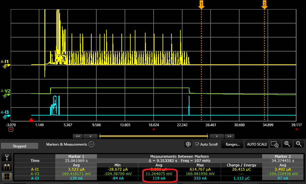
The nRF91 will automatically turn off the SIM in PSM mode. So whether or not the SIM is shut down can be measured by monitoring the voltage and current flowing through the SIM_1V8 pin, which is exposed on the DK through the "SIM current measurement" header. Below is a plot showing the SIM card in clock stop mode, then completely shut down in PSM.
This also means that another way of checking if the modem entered PSM or not is to measure the voltage on SIM_1V8
SIM in clock stop mode:
- Yellow is VDD
- Green is SIM_1V8 voltage
- Blue is SIM_1V8 current
SIM shut down:
If you have any issues or questions regarding current measurements, please create a new support ticket in the QA section: https://devzone.nordicsemi.com/f/nordic-q-a
