
Objectives
- Provide a brief primer to NCS and Zephyr
- Provide a quick-start guide to adding peripherals to an existing sample project
- Demonstrate running both foreground and background tasks within Zephyr
When starting with nRF Connect SDK and Zephyr, there are many well-documented resources to wade through. This document aims to allow you to temporarily skip to the “good parts” and at the same time guide you where to find the necessary details.
This blog will provide a high-level, incomplete, and sometimes over generalized answer regarding adding a peripheral to your project. If any information contained within this document is contradicted by referenced documentation, the reference documentation is assumed to be more accurate.
It’s assumed the reader has already installed nRF Connect SDK and the required Toolchain. If not, you should begin with Installing the nRF Connect SDK Through nRF Connect for Desktop. The reader should already know how to build an NCS Zephyr project and understand the connection between the repositories in the nRF Connect by Nordic Semiconductor GitHub organization and the files installed on the development system.
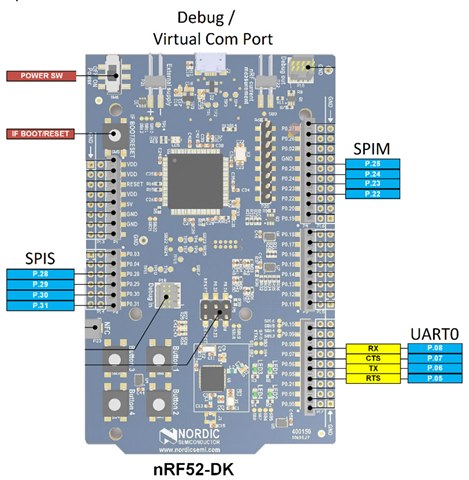
The tutorial portion of this document is based on NCS version 1.4.2 and the nRF52-DK. The tutorial will demonstrate how to start with a minimal sample project and add support for an SPI Slave (SPIS) and Master (SPIM). The provided code sends a data string from SPIM and, with external loopback, receives it from the SPIM through the SPIS. The strings SPIM sends, and SPIM receives are written to the nRF52-DK’s virtual comm port and UART0.
The SPIM and SPIS tasks are executed in independent Zephyr threads.
NCS and Zephyr
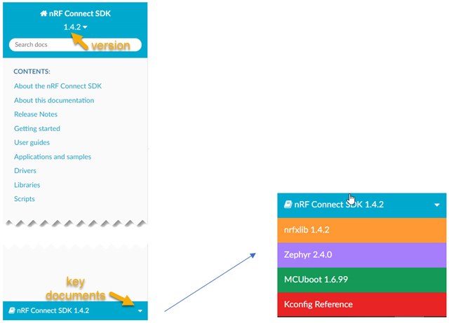
For complete information, the best place to start is Welcome to the nRF Connect SDK. From there, use the pull-down in the lower-left corner to access other essential reference resources.
The content of the resource pages shown in the next figure changes according to the version selected under the page’s title. Select the version of the nRF Connect SDK matching the version installed on your development system. Documentation for other resources, like Zephyr, will automatically be set to the correct versions for that nRF Connect SDK release.
The Zephyr distribution contains “board directories,” sometimes referred to as “board files.” Board directories describe hardware platforms. Nordic board directories are generally found in the NCS sub-directory zephyr/boards/arm. The Nordic naming convention for board directories is hardware_device. For example, the board directory nrf52804dk_nrf52840 contains a collection of files describing the nrf52840-QIAA on the nRF52840-DK.
Zephyr uses various build tools to define and configure the hardware before main() is called. Devicetree files describe the hardware and its boot-time configuration. Kconfig files describe which software features will be used and their configuration. However, there are several other files needed to complete a full description of any hardware platform.
Each board directory contains devicetree source (.dts) files. Initially, consider .dts files as a method to describe various peripherals of the target device and hardware. For more details, Introduction to devicetree is a highly recommended reading.
It is good practice not to edit devicetree files in board directories. When .dts configuration changes are needed, using devicetree overlays is recommended. A simple implementation is to create a boards/<BOARD>.overlay file in the application folder. For example, the Bluetooth: HCI UART sample in zephyr/samples/bluetooth/hci_uart contains a devicetree overlay for the nRF52840-DK in boards/nrf52840dk_nrf52840.overlay. One might consider .dts files as the default platform description and .overlay files as description modifiers.
Board directories also contain Kconfig files. Each <BOARD>_defconfig file, like nrf52840dk_nrf52840_defconfig, contains default software configuration for a board. These files’ contents are described in the Kconfig guide, and the macros are defined in Kconfig Reference.
It is also good practice not to edit <BOARD>_defconfig files. Instead, application .conf files like prj.conf and boards/nrf52840dk_nrf52840.conf are software configuration modifiers.
Adding Peripherals
This exercise uses the nRF52-DK, zephyr/samples/basic/minimal sample application, and the devicetree source (.dts) for the Sparkfun nRF52832 breakout. Starting with the Sparkfun nRF2832 breakout .dts forces us to add peripherals that are otherwise standard in most nRF52-DK examples. The resulting code will run on either the Sparkfun nRF52832 breakout or the nRF52-DK.
Unlike the nRF52-DK, the Sparkfun nRF52832 Breakout does not include the external components necessary to operate the DCDC. Enabling the DCDC on a Nordic device that is not connected to the required external components for the DCDC will disable the device, and recovery may be impossible. Therefore, unless external inductors are added to the Sparkfun nRF52832 breakout, it is essential to ensure the executable does not attempt to enable the DCDC (See Step 9 below for details).
This exercise will include and configure the UART connected to the development kit’s virtual comm port, SPIM, and SPIS. The pins used for the debug port are defined in devicetree. Respectively, pins 25, 24, 23, and 22 have been chosen for SPIM MOSI, MISO, SCLK, and SS. Pins 28, 29, 30, and 31 are used for SPIS MOSI, MISO, SCLK, and SS.
.dts and .overlay files contain trees whose nodes describe the target hardware. By comparing zephyr/boards/arm/nrf52dk_nrf52832/nrf52dk_nrf52832.dts and zephyr/boards/arm/nrf52_sparkfun/nrf52_sparkfun.dts we get some insight into how these files come together. It’s a good idea to review devicetree syntax and structure now.
The /chosen and flash (“&flash”) nodes do not need to be modified. But we need to reconfigure the uart0, spi1, and spi2 nodes. To do this, we will create a nrf52_sparkfun.overlay overlay file.
For this exercise, all directories are relative to zephyr/samples/basic/.
Step by Step:
1) Build the minimal sample for the Sparkfun nrf52832 breakout to ensure all the build tools are installed and working correctly and you have a good starting point.
2) Copy all the contents of minimal to a new directory called spi_loopback.
3) Create a text file nrf52_sparkfun.overlay and store it in a new directory spi_loopback/boards.
4) Copy the following uart0 configuration from nrf52dk_nrf52832.dts, without the additional arduino_serial node label, to the new nrf52_sparkfun.overlay. The uart0 node is already configured to present data on the nRF52-DK’s virtual com port and does not need modification.
&uart0 {
	status = "okay";
	compatible = "nordic,nrf-uart";
	current-speed = <115200>;
	tx-pin = <6>;
	rx-pin = <8>;
	rts-pin = <5>;
	cts-pin = <7>;
};
5) To add the SPIs, review dtsi, which is included by nrf52dk_nrf52832.dts, for clues. We can see that we need to create a node that is compatible with “nordic,nrf-spim,” and “nordic,nrf-spis” and change their status to “okay” (enabled). Add the following to nrf52_sparkfun.overlay:
&spi1 {
compatible = "nordic,nrf-spis";
status = "okay";
};

&spi2 {
    	compatible = "nordic,nrf-spim";
    	status = "okay";
};
6) There must be more to these nodes. So let’s review the devicetree SPI bindings. The common SPI property definitions for nRF SoCs and the nordic,nrf-spis binding that includes them collectively indicate csn-pin, def-char, sck-pin, mosi-pin, and miso-pin are required. Modify the spi1 node to reflect the previously mentioned pin assignments. Let’s also include the optional def-char configuration.
&spi1 {
compatible = "nordic,nrf-spis";
	status = "okay";
    	sck-pin = <30>;
    	mosi-pin = <28>;
    	miso-pin = <29>;
	csn-pin = <31>;
	def-char = <0xC3>;
};
7) Similarly, nrf-spim requires sck-pin, mosi-pin, and miso-pin. Let’s also include to the optional cs-gpios to drive a chip select pin.
&spi2 {
    compatible = "nordic,nrf-spim";
    status = "okay";
    sck-pin = <23>;
    mosi-pin = <25>;
    miso-pin = <24>;
    cs-gpios = <&gpio0 22 GPIO_ACTIVE_LOW>;
};
8) Save nrf52_sparkfun.overlay to spi_loopback/boards.
9) Searching the Kconfig reference to see the available config_spi options, we find the following are required. Copy the following text to a new file and save it as spi_loopback/prj.conf:
CONFIG_SPI=y

CONFIG_SPI_1=y
CONFIG_SPI_SLAVE=y
CONFIG_SPI_1_OP_MODES=2

CONFIG_SPI_2=y
CONFIG_SPI_2_OP_MODES=1
CONFIG_SOC_NRF52832_ALLOW_SPIM_DESPITE_PAN_58=y
You may not find the CONFIG_SOC_NRF52832_ALLOW_SPIM_DESPITE_PAN_58 macro in your search of Kconfig.reference. For this demo to work, this macro is required.
If you would like to run the application on a Sparkfun nRF52832 breakout that is built for the nrF52-DK, add CONFIG_BOARD_ENABLE_DCDC=n
10) Recall that uart0 was described in nrf52_sparkfun.dts. Let’s rebuild the spi_loopback project. If you are using SES, it is recommended that you close and reopen SES after making any modification to prj.conf or .overlay files. Depending on the method you used to rebuild the project, review the build_nrf52_sparkfun/zephyr/zephyr.dts or build/zephyr/zephyr.dts files and validate that nodes uart0, spi1, and spi2 are configured as desired.
11) Make the external SPIS/SPIM connections described earlier to your hardware platform. You use either the virtual com or the UART0. However, this has only been tested using the virtual com port.
12) The purpose of this exercise was to explain how o add peripheral to an existing project. Having completed this task, the loopback code is provided. Replace spi_loopback/main.c with the attached code.
13) Com port settings are 11500, 8N1. The SPIS will not be ready when the first message is sent from the SPIM, so do not be concerned by the initial SPIS not available message. Because the slave does not provide or change the index, the initial slave message received by the master does not contain a numerical index.
nRF Connect SDK v1.7.0 Update
new prj.conf
#
# Copyright (c) 2020 Nordic Semiconductor ASA
#
# SPDX-License-Identifier: LicenseRef-BSD-5-Clause-Nordic
#

CONFIG_SPI=y
CONFIG_SPI_SLAVE=y

#CONFIG_SPI_1=y
#CONFIG_SPI_1_OP_MODES=2
CONFIG_NRFX_SPIS1=y

#CONFIG_SPI_2=y
#CONFIG_SPI_2_OP_MODES=1
CONFIG_NRFX_SPIM2=y

CONFIG_SOC_NRF52832_ALLOW_SPIM_DESPITE_PAN_58=y
With nRF Connect SDK V1.7.0, the SPIS Thread is being serviced more often than the SPIM is sending a message. As a result, an SPIS error message occurs when attempting to send an empty SPIS buffer.
The simplest solution is to remove lines 211 and 212
else
 printk("SPIS error %i\n", cnt);
from main.c
However, the best solution would be to change the SPIS Thread to sleep after transmitting all previously received data and waking up when the SPIS buffer is filled with new data. Doing this is currently beyond the scope of this blog. But if you are interested in understanding how this could be implemented, please refer to the peripheral_uart sample project.
Final Thought
You should now have a good start at understanding the basics of setting up and configuring an NCS project. As you work with NCS and Zephyr, you will find multiple ways of accomplishing these tasks. Whatever paths you choose, the best way to confirm that the project was configured as expected is to review build/zephyr/zephyr.dts and build/zephyr/.config.
Addendum:
The source was created by referring to these resources.
If you found this blog of value, you may want to also review TWI/I2C implementation with nRFx TWIS Driver.