


Power Management Integrated Circuits (PMICs) play a crucial role in modern electronics, especially in battery-powered and portable devices. As embedded systems become more complex and energy efficiency becomes increasingly important, designers rely on advanced PMICs to manage power distribution, battery charging, and system monitoring. Nordic Semiconductor’s nPM Series of PMICs is widely recognized for its integration, flexibility, and low-power features, making it a popular choice for wireless and IoT applications. While these PMICs are often paired with Nordic’s own SoCs, many developers seek to integrate them with non-Nordic microcontrollers to take advantage of their robust feature set.
In this blog post, we will implement a Nordic Semiconductor PMIC with a non-Nordic SoC. The goal is to understand what is needed from a software platform to integrate any Nordic Semiconductor PMIC into your design. This blog will be split into two sections: one for integrating the npmx drivers and the second for implementing the PMIC's fuel gauging capabilities. Although this blog is targeted at the nPM1300, the information is viable for any nPM device.
For reference, a test project was created using an STM32F401 MCU with FreeRTOS in the CubeMX IDE from ST.
Table of Contents
Background
Nordic Semiconductor’s Power Management IC (PMIC) portfolio is designed to deliver maximum energy efficiency, high integration, and seamless development across battery‑powered IoT products. All Nordic Semiconductor PMICs are optimized to pair with Nordic nRF52, nRF53, nRF54, and/or nRF91 wireless SoCs, but can also be used with other non-Nordic SoCs that have either Cortex-M4, Cortex-M3, or Cortex-M33 architectures.
The nPM1300 is a highly integrated Power Management IC (PMIC) for rechargeable applications. The nPM1300 has several power and system management features that can be implemented with dedicated components. Power management is achieved through flexible power regulation and a linear-mode lithium-ion (Li-ion), lithium-polymer (Li-poly), and lithium iron phosphate (LiFePO4) battery charger.
nPM1300 supports charging up to 800 mA and delivers up to 500 mA of adjustable regulated voltage. Power is supplied to external components from two configurable, dual-mode 200 mA BUCK regulators and two dual-purpose 50 mA LDO/100 mA load switches. Unregulated, an unregulated power rail delivers up to 1340 mA when powered from a battery, or up to 1.5 A when powered from a USB port configured as DCP.
The host can read the battery's temperature, voltage, and current, which are used by a fuel gauge algorithm. The fuel gauge provides the application with a battery state-of-charge estimate comparable to Coulomb counters, with significantly lower power consumption.
The integrated system management features reduce the cost and size of applications. The following integrated features are found in the device:
-
System-level watchdog
-
Intelligent power-loss warning
-
Ship and Hibernate modes for increased battery life
-
Up to 5 GPIO pins and 3 LED drivers
-
System Monitor
-
Ultra-low power, high accuracy fuel gauge tailored for embedded IoT applications
System management features and I/Os are configured through an I2C compatible two-wire interface (TWI).
Development with npmx drivers
To begin development with an nPM device and the npmx drivers, you will need to clone the driver repository. The npmx drivers can be found at this GitHub link: https://github.com/NordicSemiconductor/npmx/tree/v1.2.0
Once you clone the npmx GitHub repository, you should have a directory structure like this:
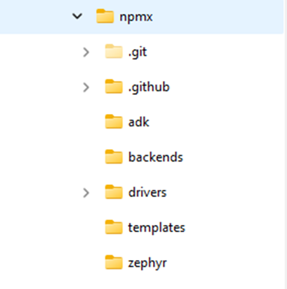
The main folders that are used when not in a Zephyr environment are the folders adk, backends, and drivers.
The adk folder contains the header files needed for the nPM1300 and nPM1304. These header files contain the register addresses and structure declarations used in other areas of the code. These specific files are included when you add #include <npmx.h>.
The backends folder contains the structure definitions for the backend that include the pointers to the read and write I2C functions.
The drivers folder includes the source code needed for each module of the nPM family. This includes the core, ADC, charger, GPIO, and other feature sets of the PMIC.
The npmx GitHub repository includes a porting guide to help get started developing with the npmx drivers. https://github.com/NordicSemiconductor/npmx/blob/v1.2.0/PORTING.md
One of the key things highlighted in the porting guide is to link the SoC I2C functions with the npmx drivers. The porting guide shows a function call to initialize the nPM core, but also to link the backend data structures to the read and write function calls.
You will need to define the npmx_instance and npmx_backend structures. These are used as handles by the npmx driver functions and the I2C backend, associating a particular I2C read/write function with an instance of the npmx pmic driver.
This is an excerpt from the porting guide.
static npmx_instance_t npm1300_instance;
static npmx_backend_t npm1300_backend;

static npmx_error_t my_i2c_write_function(void * p_context, uint32_t register_address, uint8_t * p_data, size_t num_of_bytes);
static npmx_error_t my_i2c_read_function(void * p_context, uint32_t register_address, uint8_t * p_data, size_t num_of_bytes);
The porting guide then shows how to initialize the npmx driver core, which associates the instance and backend structures and initializes the core functionality of the nPM device.
static void my_npmx_initialization_function(void)
{
    //Associate the I2C Read and Write to backend data structure used in npmx drivers
    npm1300_backend.p_read = my_i2c_read_function;
    npm1300_backend.p_write = my_i2c_write_function;
    npm1300_backend.p_context = NULL; // Optional context for our use

    npmx_error_t npmx_err = npmx_core_init(&npm1300_instance, &npm1300_backend, NULL, true);
    // TODO: Verify that npmx_err == NPMX_SUCCESS
}
Since we are using an STM32 in the blog post, the read and write function calls are as follows. These calls will vary depending on the SoC and libraries you use in your project, and whether you use the SDK HAL or write your own.
npmx_error_t my_i2c_write_function(void * p_context, uint32_t register_address, uint8_t * p_data, size_t num_of_bytes)
{
    uint8_t tx_buffer[ I2C_BUF_SIZE ] = { 0 };
    npmx_error_t ret;
    HAL_StatusTypeDef stm_ret;

    tx_buffer[ 0 ] = ( uint8_t ) ( ( register_address >> 8 ) & 0xFF );
    tx_buffer[ 1 ] = ( uint8_t ) ( register_address & 0xFF );

    for (uint8_t cnt = 0; cnt < num_of_bytes; cnt++)
    {
      tx_buffer[ cnt + 2 ] = p_data[ cnt ];
    }
    stm_ret = HAL_I2C_Master_Transmit(&hi2c1, NPM13xx_ADDR << 1,tx_buffer,num_of_bytes+2, TIMEOUT );

    if (stm_ret != HAL_OK) {
      ret = NPMX_ERROR_INVALID_PARAM;
    } else {
      ret = NPMX_SUCCESS;
    }

    return ret;
}
npmx_error_t my_i2c_read_function(void * p_context, uint32_t register_address, uint8_t * p_data, size_t num_of_bytes)
{
uint8_t rx_buffer[ 2 ] = { 0 };
npmx_error_t ret;
HAL_StatusTypeDef stm_ret;
rx_buffer[ 0 ] = ( uint8_t ) ( ( register_address >> 8 ) & 0xFF );
rx_buffer[ 1 ] = ( uint8_t ) ( register_address & 0xFF );
stm_ret = HAL_I2C_Master_Transmit(&hi2c1, NPM13xx_ADDR << 1,rx_buffer,2, TIMEOUT);
if (stm_ret != HAL_OK) {
ret = NPMX_ERROR_INVALID_PARAM;
} else {
ret = NPMX_SUCCESS;
}
stm_ret = HAL_I2C_Master_Receive(&hi2c1,NPM13xx_ADDR<< 1, p_data, num_of_bytes, TIMEOUT);
if (stm_ret != HAL_OK) {
ret = NPMX_ERROR_INVALID_PARAM;
} else {
ret = NPMX_SUCCESS;
}
return ret;
}Note that the return type of the my_i2c_read_function and my_i2c_write_function are of type npmx_error_t. The return type from the I2C functions of the SoC you are targeting are not of the same type. It is necessary to make a simple translation of the return type of the I2C call with the npmx_error_t type.
Now that we have a framework for I2C communication, no additional direct I2C transfer calls are needed to access the functionality of the nPM device. Within the framework of the npmx drivers, there are independent function calls for each module in the nPM device. Looking in the drivers folder, you will find source code for each module: ADC, BUCK, GPIO, VBUS, etc.
When selecting a module you want to utilize, you just need to reference the npmx_instance structure you already defined to the data structure used in each module. For example, if you are interested in using the features of the charger in the nPM1300, you use the npmx_charger_get() function call with the npmx_instance struct that has previously been defined and initialized using the npmx_core_init() function. The npmx_charger_get() function returns a handle of type npmx_charger_t, which is then used as an argument in other npmx_charger_<xxx> () functions.
npmx_charger_t * charger = npmx_charger_get(&npm1300_instance, 0);
get() call.So, for each module you are looking to utilize, you need to make a call to the npmx_<xxx>_get() function call to retrieve the data structure for that module associated with the top-level npmx_instance.
Now you can pass the new data structure to the function calls within that module.
For example, after you define a charger data structure like above, you can access all the features of the charger by passing the charger data structure in the function call. By doing this, you are referencing the I2C function calls defined in your code earlier in the my_npmx_initialization_function(void) function. The code below enables or disables the charger, sets termination voltages, and sets charging current by passing the data structure *charger to each function call.
// Disable charger before changing charge current.
    ret = npmx_charger_module_disable_set(charger,NPMX_CHARGER_MODULE_CHARGER_MASK );

    // Set charging current.
    charger->charging_current_ua = NPM_BCHARGER_CHARGING_CURRENT_DEFAULT;
    ret = npmx_charger_charging_current_set(charger, charger->charging_current_ua);

    /* Set maximum discharging current. */
    charger->discharging_current_ma = NPM_BCHARGER_DISCHARGING_CURRENT_DEFAULT;
    ret = npmx_charger_discharging_current_set(charger, charger->discharging_current_ma);

    // Set battery termination voltage in Normal and Warm temperature.
    ret =npmx_charger_termination_normal_voltage_set(charger, npmx_charger_voltage_convert(4200));  //4.2V
    /* Set battery termination voltage in warm temperature. */
    ret =npmx_charger_termination_warm_voltage_set(charger, npmx_charger_voltage_convert(4000));  //4.0V

    // Enable charger for events handling.
    ret = npmx_charger_module_enable_set(charger,NPMX_CHARGER_MODULE_CHARGER_MASK | NPMX_CHARGER_MODULE_RECHARGE_MASK );
You can poll the nPM device via I2C, use I2C-only Task execution, have direct hardware control of the PMIC via GPIOs, or use the nPM device's GPIOs to generate an interrupt to the host SoC.
1. Polling via I2C
Instead of relying on an interrupt signal to wake the host SoC, you can manually poll the nPM1300's event registers over the I2C interface.
-
How it works: You can read the EVENTS* registers (such as EVENTSVBUSIN0SET at 0x16 or EVENTSGPIOSET at 0x22) to check if a specific event has occurred.
-
Limitation: Polling is generally less power-efficient than interrupt-driven designs because the host MCU must remain active or wake up periodically to check the registers, rather than staying in a deep sleep state until a signal is received.
2. Direct hardware control (Control Input mode)
If you intend to use GPIOs for control logic rather than status reporting, you can configure the nPM1300 GPIOs as Control Inputs instead of interrupt triggers. [Pin configuration].
-
Functionality: In this mode, a physical pin on the nPM1300 can directly control internal components without involving the host SoC’s software or interrupts. For example, a GPIO can be configured to:
-
Enable/disable BUCK regulators via BUCKENCTRL
-
Control Load Switches (LDSW) via LDSW1GPISEL or LDSW2GPISEL
-
Select voltage levels for active and retention modes.
-
3. I2C-only task execution
Some tasks, such as kicking the Watchdog Timer (WDT) on the nPM1300, cannot be triggered by a GPIO; they must be performed exclusively via the I2C interface. If your application already requires frequent I2C communication, you might find that managing events via I2C fits your existing architecture without needing a dedicated interrupt line.
4. GPIO interrupt generation
By setting a pin's GPIOMODE to GPOIRQ, the PMIC will pull the line high when a configured system event occurs. All system events share the same GPIO; once triggered, the host must read the PMIC's event registers over I2C to determine the cause. A GPIO can be specifically assigned to indicate an imminent power failure warning and a GPIO can indicate when the internal watchdog timer expires.
Important note on power consumption
If you are trying to minimize power consumption (e.g., reaching the 4–5 µA range), using GPIO interrupts on the host MCU can sometimes increase current draw if not configured correctly. If you avoid the interrupt line, you ensure the host can stay in a low-power state, but you will lose the ability for the PMIC to "wake up" the host immediately when an event (like VBUS insertion or a battery error) occurs.
In the project developed for this blog using the STM32, the GPIO interrupt generation method was used. A GPIO on the nPM device was used to generate an interrupt to the host SoC. This PMIC GPIO must be configured to generate interrupts by setting GPIOMODE to GPOIRQ. It is then connected to a host processor GPIO, which must be configured to generate interrupts upon a level change from the nPM device.
The application must provide callback functions for each interrupt type it wants to receive and enable these interrupts. Callbacks are also created for each event enabled on the nPM device.
Use the npmx_core_register_cb and npmx_core_event_interrupt_enable functions for this.
An example of creating multiple callbacks and enabling interrupts is shown in the code below.
/* register callbacks for all events of the nPM*/
    /* Register callback for VBUS events. */
    npmx_core_register_cb(&npm1300_instance, vbus_callback, NPMX_CALLBACK_TYPE_EVENT_VBUSIN_VOLTAGE);
    /* Register callback for ADC events. */
    npmx_core_register_cb(&npm1300_instance, adc_callback, NPMX_CALLBACK_TYPE_EVENT_ADC);
    /* Register callback for battery events. */
    npmx_core_register_cb(&npm1300_instance, charger_battery_callback, NPMX_CALLBACK_TYPE_EVENT_BAT_CHAR_BAT);
    /* Register callback for charger status events. */
    npmx_core_register_cb(&npm1300_instance, charger_status_callback,  NPMX_CALLBACK_TYPE_EVENT_BAT_CHAR_STATUS);


//  Enable USB connections interrupts and events handling.
    npmx_core_event_interrupt_enable(&npm1300_instance, NPMX_EVENT_GROUP_VBUSIN_VOLTAGE, NPMX_EVENT_GROUP_VBUSIN_DETECTED_MASK |
                NPMX_EVENT_GROUP_VBUSIN_REMOVED_MASK);

    /* Enable all charging status interrupts and events. */
    npmx_core_event_interrupt_enable(
        &npm1300_instance, NPMX_EVENT_GROUP_BAT_CHAR_STATUS,
        NPMX_EVENT_GROUP_CHARGER_SUPPLEMENT_MASK | NPMX_EVENT_GROUP_CHARGER_TRICKLE_MASK |
            NPMX_EVENT_GROUP_CHARGER_CC_MASK | NPMX_EVENT_GROUP_CHARGER_CV_MASK |
            NPMX_EVENT_GROUP_CHARGER_COMPLETED_MASK |
            NPMX_EVENT_GROUP_CHARGER_ERROR_MASK);

    /* Enable battery interrupts and events. */
    npmx_core_event_interrupt_enable(&npm1300_instance, NPMX_EVENT_GROUP_BAT_CHAR_BAT,
                     NPMX_EVENT_GROUP_BATTERY_DETECTED_MASK | NPMX_EVENT_GROUP_BATTERY_REMOVED_MASK);

    /* Enable ADC measurements ready interrupts. */
    npmx_core_event_interrupt_enable(&npm1300_instance, NPMX_EVENT_GROUP_ADC, NPMX_EVENT_GROUP_ADC_BAT_READY_MASK);
When an interrupt is detected on the host processor side, the npmx driver must be informed of this using the npmx_core_interrupt function. This sets a flag in npmx. The actual interrupt processing happens when the npmx_core_proc function is called. It reads and clears the event registers and triggers callback functions registered by the application.
npmx_core_interrupt(&npm1300_instance); //This sets a flag in npmx
err=npmx_core_proc(&npm1300_instance);  //Process the interrupt
The attached project has a GPIO ISR that simply sets a flag and calls npmx_core_interrupt(). Then TASK01 processes and the flag with the call to npmx_core_proc().
Fuel gauge
Nordic’s fuel gauging solution for nPM PMICs is based on a battery model plus the Nordic fuel gauge algorithm running on a host SoC.
In Nordic’s nPM PMICs, fuel gauging is the function that estimates a battery’s state of charge (SoC, 0–100%) using measurements plus a battery‑specific model, instead of just reading voltage.
For nPM1300 and nPM1304 (rechargeable batteries):
-
The PMIC measures battery current, voltage, and temperature.
-
A battery model (created once by profiling your specific cell in the nPM PowerUP PC app) mathematically describes how that battery behaves. [nPM1300/1304 FG overview]
-
A fuel‑gauge algorithm running on a host SoC (e.g. nRF52, nRF53, nRF54, nRF91) combines the live measurements with the model to give a stable, temperature‑compensated SoC estimate, typically within ±3% error under rated conditions.
For nPM2100 (primary, non‑rechargeable cells like AA/AAA/CR):
-
Nordic provides a fuel gauge algorithm that runs on an Arm Cortex‑M4/M33 SoC (e.g. nRF52, nRF53, nRF54) to estimate SoC for alkaline AA/AAA and Li‑MnO₂ coin cells. [nPM2100 FG intro]
-
It uses a battery model that averages voltage and resistance behavior across cells to standardize SoC estimation for primary batteries. [nPM2100 battery model]
-
The algorithm is designed for ultra‑low power, running only during active periods so it does not force extra wakeups. [nPM2100 power consumption]
In short, fuel gauging in nPM devices is Nordic’s model‑based, ultra‑low‑power method for accurately tracking how much usable energy remains in your battery, rather than just measuring voltage.
To enable the fuel gauge algorithm on your SoC, you must integrate both the battery model and the nRF Fuel Gauge library into your project.
To incorporate a battery model into your design, you can choose from one of the following three options:
-
Create a custom profile: Generate a profile for your specific battery using the nPM PowerUP app within the nRF Connect for Desktop suite.
-
Export from the App library: Use the nPM PowerUP PC app to export a battery_model.inc file from its existing list of pre-profiled battery models.
-
Use standard Nordic models: Utilize ready-made .inc battery models provided by Nordic for selected Renata Li-Po cell (e.g.,
ICP641620PA01.inc,ICP621333PA01.inc), which you can download directly and use asbattery_model.incin your project. [Fuel gauging models].
To include the battery_model.inc file in your code you need to call it within the battery_model structure.
static const struct battery_model battery_model = {
#include "battery_model.inc"
};
To incorporate the Fuel Gauge Library into your design, you will need to find the specific algorithm you intend to use for the host SoC. The various libraries are located in https://github.com/nrfconnect/sdk-nrfxlib/tree/main/nrf_fuel_gauge . You can choose which Cortex device you use and whether to use hard or soft float. When using the nPM130x series, include the libnrf_fuel_gauge.a file and when using the nPM2100 use the libnrf_fuel-gauge_primary.a.
Note: When using IDE tools like STM cube or NXP MCUexpresso, there are a few restrictions on how libraries are included in their projects. Typically, they do not allow the .a suffix or the name of the file to start with lib. So when using the STM Cube, I changed the library name to nrflib_fuel_gauge without the .a suffix.
You will need to copy the nrf_fuel_gauge.h file from https://github.com/nrfconnect/sdk-nrfxlib/tree/main/nrf_fuel_gauge/include
The basic framework for the fuel gauge is found in the GitHub repository https://github.com/NordicSemiconductor/npmx-zephyr/blob/main/samples/fuel_gauge/src/fuel_gauge.c
This repository is targeted at using the npmx drivers in the Zephyr environment. Since this blog is intended to use the nPM130x device outside Zephyr, some modifications were made to that code to remove Zephyr-specific function calls.
The two main functions required to use the fuel gauge are the fuel_gauge_init() and fuel_gauge_process() calls.
When calling the fuel_gauge_update() function, this will in turn call nrf_fuel_gauge_process() function, you must provide a t_delta value (as a float) [nRF Fuel Gauge API]. This value must be the time difference between the previous gauge update and the current update, not the time elapsed since the system started.
While the library does not strictly require measurements at a fixed interval, the following frequencies are recommended based on device activity:
-
Active State: Run the algorithm once every 1 second
-
Charging: Recommended interval of 0.5 seconds
-
Idle State: Run every 5 seconds
-
Ultra-Low Power: For extremely low power consumption, it is possible to wake up and call the process function every 10 minutes or more
If the current consumption is too low to be measured accurately by the PMIC (e.g., microamp range), you can use nrf_fuel_gauge_idle_set() to inform the library of the expected current instead of performing iterations.
Additionally, accuracy can be optionally enhanced by informing the library of external events, such as battery charging state. Use the nrf_fuel_gauge_ext_state_update() function for this purpose.
Closing
The project for this blog was based on the STM32F401 and utilized the nPM1300's standard operations and fuel gauge capabilities. The repository can be found here: https://github.com/WesC-sys/Blog-STM32-nPM1300
There are several function calls to demonstrate the core and peripheral functionality of the nPM1300 while also implementing the fuel gauge. This project has two Tasks running; Task01 has both the fuel gauge and event system implemented. It will show the state of the battery from the fuel gauging and only show an event output when an event occurs with the battery. Task02 simply outputs that it has entered the Task.
This blog post demonstrates how Nordic’s nPM Series PMICs can be integrated with third-party SoCs. By leveraging npmx Drivers and the fuel gauge library and algorithm, the nPM PMIC can be added to any SoC design.
