


The Thread protocol is a reliable, secure, and scalable solution for low-power IoT devices. One of the important aspects of its implementation is drawing as little power as possible. This ensures a long lifetime for battery-powered devices, making them convenient to use for end users.
Thread takes low power consumption for end devices to the next level by creating Sleepy End Devices (SED) and Synchronized Sleepy End Device (SSED) modes for Minimal Thread Devices. In both of these modes, the radio transceiver is normally disabled. For an SED, the transceiver wakes up periodically to poll the parent for any pending data, meaning it sleeps most of the time. In SSED mode, devices are further optimized for power consumption. The polling period is increased, and between polling, the device wakes only to listen for incoming messages from the parent, which reduces the need to send data requests each time. For more information, see Sleepy End Device types in Thread.
In this blog post, we present a step-by-step guide for configuring devices to SED and SSED mode and measuring their power consumption using Nordic’s development kits. Then, we will present the results from our measurements along with estimates of battery life for these devices.
The conducted tests assume that the Minimal Thread Device in SED or SSED mode only listens to a parent with a frequency of one second, but no data is exchanged.
Table of Contents
Hardware and network setup
1. Flash the parent platform with the Thread CLI sample, available in the nRF Connect SDK repository (v2.4.1 release was used for this blog post).
Commands used to build the firmware:
cd ncs/nrf/samples/openthread/cli/
west build -b nrf52840dk_nrf52840
2. For the child platform, you must build the firmware with low-power overlays found in the sample. These overlays ensure that unused components are powered down. They also cause the device to enter super low power mode (by disabling serial communication and powering down unused RAM) after connecting to the Thread network.
Commands used to build the child firmware (replace build-target with the build target name of the tested platform):
cd ncs/nrf/samples/openthread/cli/
west build -b build-target -- -DOVERLAY_CONFIG="overlay-ci.conf;overlay-low_power.conf" -DDTC_OVERLAY_FILE="low_power.overlay"
3. After flashing the devices, connect to the parent platform by opening a serial port with baudrate set to 115200 and configure it with the required parameters:
uart:~$ ot channel 11
Done
uart:~$ ot panid 0xabcd
Done
uart:~$ ot networkkey 00112233445566778899aabbccddeeff
Done
4. Start the network using the following commands:
uart:~$ ot ifconfig up
Done
uart:~$ ot thread start
Done
5. Before configuring the child platform, you must connect it to the Power Profiler Kit II (PPK2)
The VOUT Pin from the PPK2 should be connected to ‘+’ and the GND Pin to ‘-’ of the external supply connector on the development kit. VEXT > nRF switch (SW10) should be in the ON position. Open the Power Profiler app, available in nRF Connect for Desktop, and set the PPK2 to Source Meter mode with the supply voltage set to 3000 mV. See the PPK2 User Guide for more information.
5. Configure the child device as either an SED or SSED, by connecting it to serial port, described for the parent platform above.
5a. The following commands configure the device as an SED. They set the child to poll for data from the parent every 1 second, and disable child supervision.
uart:~$ ot channel 11
Done
uart:~$ ot panid 0xabcd
Done
uart:~$ ot networkkey 00112233445566778899aabbccddeeff
Done
uart:~$ ot mode n
Done
uart:~$ ot pollperiod 1000
Done
uart:~$ ot childsupervision interval 0
Done
uart:~$ ot childsupervision checktimeout 0
Done
5b. The following commands configure the device as an SSED. They set the child to listen for data every 1 second and trigger data polling (which also synchronizes clocks between it and the parent) every 20 seconds and disables child supervision.
uart:~$ ot channel 11
Done
uart:~$ ot panid 0xabcd
Done
uart:~$ ot networkkey 00112233445566778899aabbccddeeff
Done
uart:~$ ot mode n
Done
uart:~$ ot csl period 1000000
Done
uart:~$ ot csl timeout 20
Done
uart:~$ ot childsupervision interval 0
Done
uart:~$ ot childsupervision checktimeout 0
Done
6. After configuring the child device, get its MLE IP address (which will be useful later) and start the network:
uart:~$ ot ipaddr mleid
fdde:ad00:beef:0:2ac6:1d76:c5b8:57d4
Done
uart:~$ ot ifconfig up
Done
uart:~$ ot thread start
Done
7. After the DUT attaches to the Thread network, its CLI console should become unresponsive. Then you can switch the board to nRF only mode (SW6), and ping the DUT from the parent platform, using the MLE IP address, to synchronize communication:
uart:~$ ot ping fdde:ad00:beef:0:2ac6:1d76:c5b8:57d4
16 bytes from fdde:ad00:beef:0:2ac6:1d76:c5b8:57d4: icmp_seq=1 hlim=64 time=46ms
1 packets transmitted, 1 packets received. Packet loss = 0.0%. Round-trip min/avg/max = 46/46.0
Done
8. Right after the ping, start the measurements in the Power Profiler app. The measurements should be configured for 60 seconds with 100,000 samples per second.
Results and analysis
After running the tests, the results are shown in the Power Profiler app (the example below is for SED mode), including the calculation of total charge per minute:
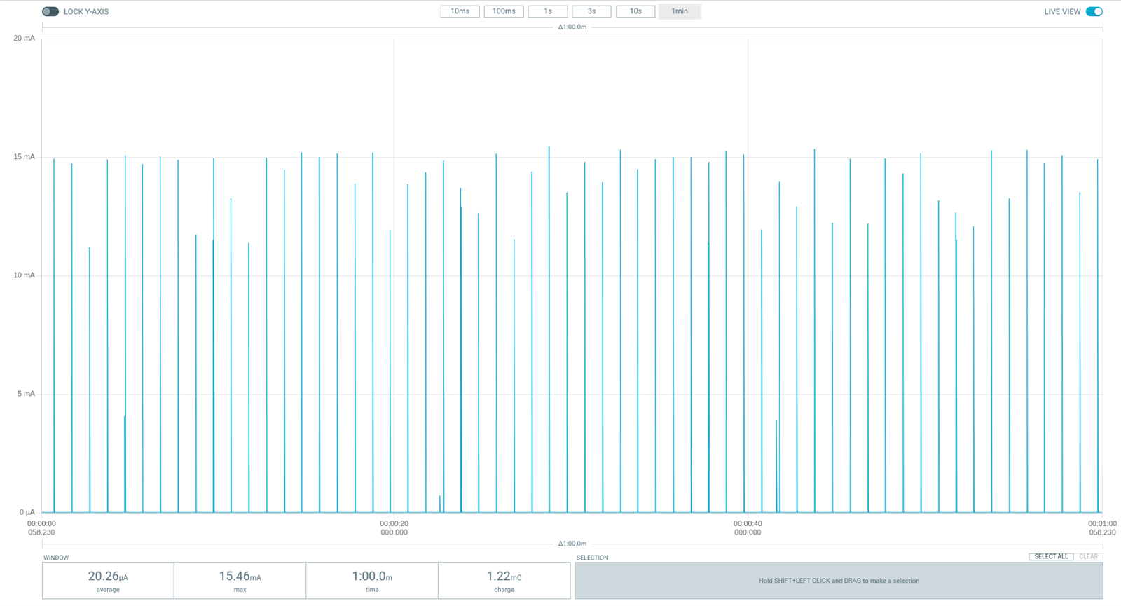
Further analysis of power consumption will be done separately for SED and SSED modes.
Results in SED mode
In SED mode, the average charge of the polling state can be extracted from measurements. It occurs every second and can be characterized as a visible increase in power consumption:
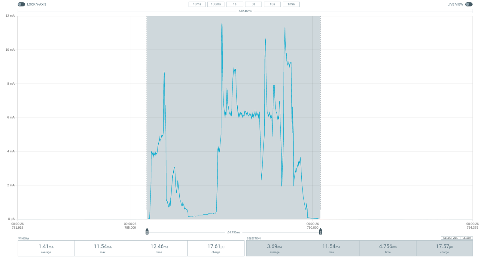
The first peak visible on the figure refers to Data Request preparation. The second part corresponds consecutively to pre-processing, Data Request, and RX state when the child gets a response from the parent and checks if there is any more pending data. The rest of the measured consumption should be treated as sleep current.
Results in SSED mode
In SSED mode, the average charge of the CSL (Coordinated Sampled Listening) receive state can be extracted from the measurements. It occurs every second and can be characterized as a visible increase in power consumption. Note that the CSL receive charge gradually increases as the RX window gets wider each time to compensate for drift between child and parent clocks. The value resets every 20 seconds when the clock is synchronized as part of data polling.
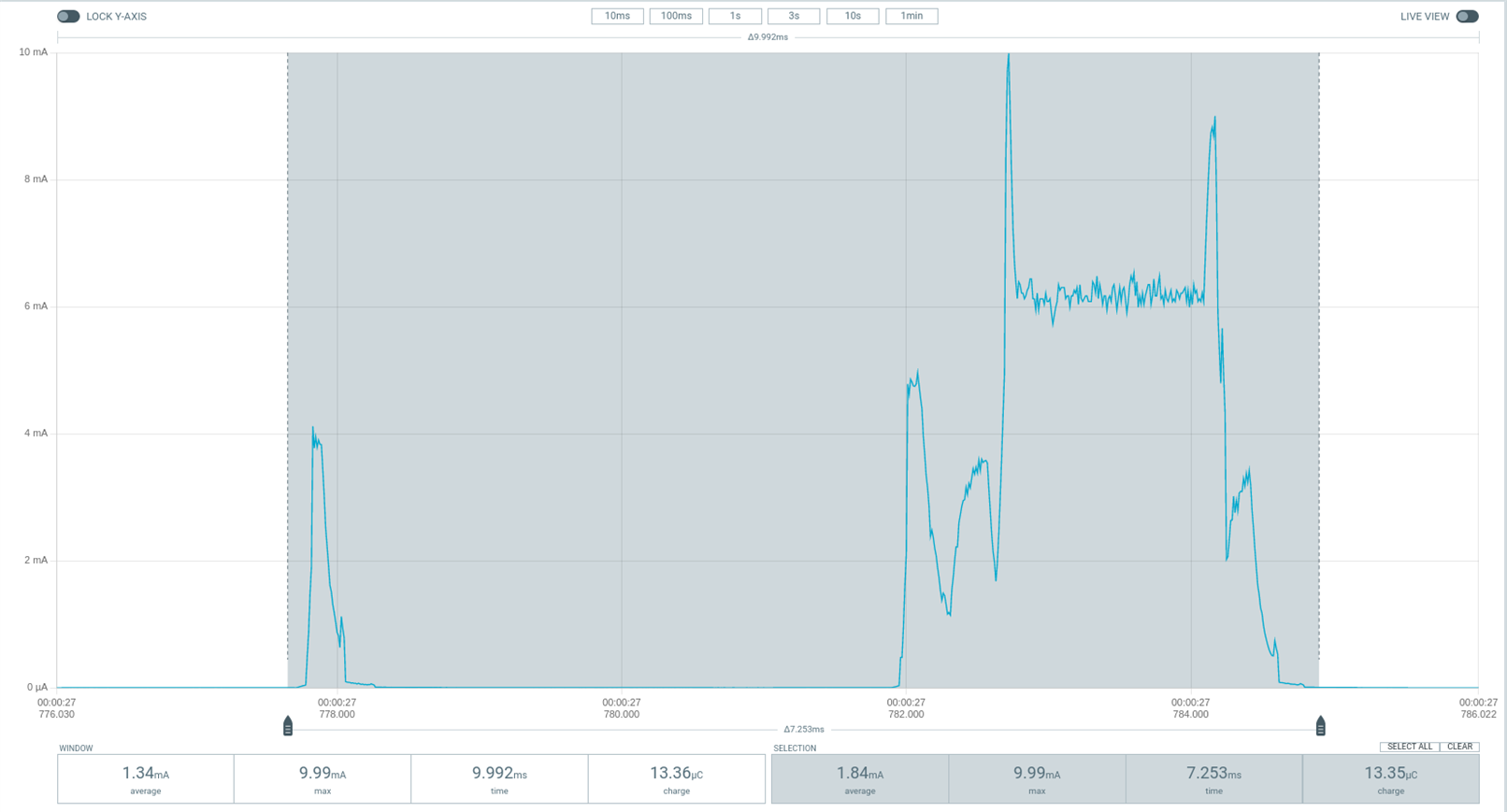
In the above picture, the first visible peak is caused by the CSL scheduler. After a few milliseconds, the child device switches to RX state, awaiting data from the parent.
Every 20 seconds, data polling occurs and can be seen in measurements, trailing the CSL receive state:
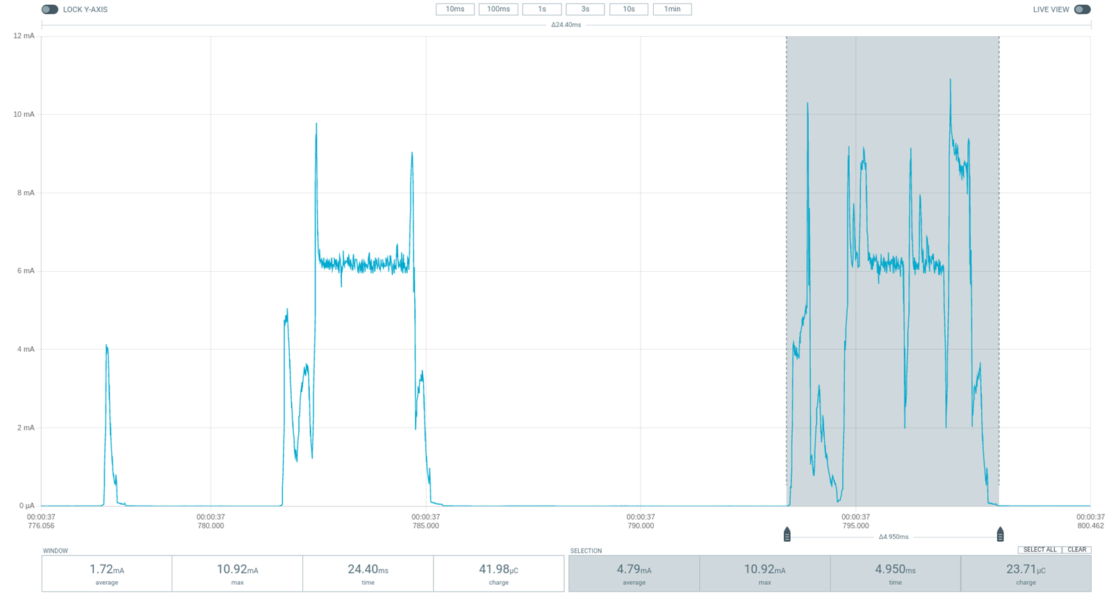
The rest of the measured consumption should be treated as sleep current.
Power consumption results
The power consumption of the nRF52840 DK development kits in SED and SSED modes was measured daily. Below are the average results from 10 consecutive tests.
SED mode
|
Parameter |
nRF52840 DK |
|
Total charge per minute [μC] |
1216.10 |
|
Average data poll charge [μC] |
17.63 |
|
Average sleep current [μA] |
2.65 |
SSED mode
|
Parameter |
nRF52840 DK |
|
Total charge per minute [μC] |
1053.70 |
|
Average CSL receive charge [μC] |
13.71 |
|
Average data poll charge [μC] |
24.06 |
|
Average sleep current [μA] |
2.70 |
Device configuration
The results presented above were taken using the following configuration for the child devices:
|
Parameter |
nRF52840 DK (SED mode) |
nRF5840 DK (SSED mode) |
|
Board revision |
V2.0.2 |
V2.0.2 |
|
Supply Voltage [V] |
3.0 |
3.0 |
|
Transmission power [dBm] |
0 |
0 |
|
Polling period [ms] |
1000 |
N/A |
|
CSL period [ms] |
N/A |
1000 |
|
CSL timeout [s] |
N/A |
20 |
|
Parent’s CSL accuracy [ppm] |
N/A |
±20 |
|
Parent’s CSL uncertainty [μs] |
N/A |
±120 |
Based on the results presented above, it can be assumed that for the specific configuration with a 1-second data exchange period, the power consumption of SSED compared to SED is lower by 11.7%. Power consumption is lower for SSED for low data exchange intervals (1 s and less), because of the higher ratio between RX and TX states in SSED mode. Because of clock accuracy, CSL timeout has been set to 20s for the above measurements since it strictly affects power consumption. Higher timeout causes higher clock drift and requires the child device to stay in RX state longer, increasing power consumption.
Battery life estimation
With the given results, we can estimate the lifetime of a device in SSED and SED mode with certain batteries. The following estimations assume ideal battery conditions throughout their lifetime. The device’s lifespan might be shorter in a real-life scenario because of factors like battery aging and self-discharge.
Let us compare estimates for two types of batteries: CR2032 with 230 mAh capacity and 2x AA with 2850 mAh capacity.
|
CR2032 battery |
nRF52840 DK |
|
|
SED |
SSED |
|
|
Average current [μA] |
20.27 |
17.56 |
|
Hours of operation [h] |
11347.75 |
13096.71 |
|
Days of operation [d] |
472.82 |
545.70 |
|
Years of operation [y] |
1.30 |
1.50 |
|
2x AA battery |
nRF52840 DK |
|
|
SED |
SSED |
|
|
Average current [μA] |
20.27 |
17.56 |
|
Hours of operation [h] |
140613.44 |
162285.28 |
|
Days of operation [d] |
5858.89 |
6761.89 |
|
Years of operation [y] |
16.05 |
18.53 |
Closing
In this post, we have covered how to implement SED and SSED power consumption tests in Thread on Nordic development kits and provided the results from tests executed by our team, together with battery life estimates.
Results show that both modes provide promising power optimization of power consumption with an estimated battery life of over one year for smaller devices with CR2032 batteries and over 13 years for bigger ones with double AA batteries, assuming ideal battery conditions throughout their lifetime.
Results also show that for the discussed configuration, SSED mode consumes 11.7% less current than SED mode, which makes it a desirable choice for devices focused on super-low power consumption.

