


During a summer internship at Nordic, I took on a project that focused on applying Bluetooth® Mesh technology in a practical setting. The project concentrated on making emergency lighting testing in commercial buildings more efficient. Traditional methods for testing these lights are time-consuming and expensive for several reasons. Each light fixture must be manually checked, a process that becomes even more arduous in large buildings with many lights. This involves verifying each light's functionality and compliance with safety standards, often requiring access to hard-to-reach areas and coordination with multiple maintenance teams. Such manual inspections can also disrupt a building's daily operations, leading to additional indirect costs. The need for specialized staff and equipment for testing and maintenance further increases expenses. Taking these challenges into consideration, I was able to prototype an automated solution based on Bluetooth Mesh technology.
In this blog, I will detail the problem addressed, explain how the solution was designed, and the implementation of Bluetooth Mesh in the solution. My aim was to create a working product quickly despite having a limited background in working with mesh networks. This blog post explores the specific problem I tackled, highlighting the suitability of Bluetooth Mesh for this purpose. I hope this encourages you to explore and solve new challenges using the Bluetooth Mesh technology and the nRF Connect SDK.
Table of Contents
Introduction
Bluetooth Mesh, with recently released Networked Lighting Control (NLC) Profiles, is set to become the most popular technology for industrial lighting. With the ease of installation, standardized features set, and low power consumption for battery-powered cases during the outage of main power supply, it can be a natural choice also for emergency lights. Consequently, when considering project ideas, centering on Bluetooth Mesh was an intuitive decision. Following an examination of different options and guided by my supervisor's advice, we chose to concentrate on a practical application: meeting a particular safety need in public buildings.
Use case
Public buildings are mandated to meet certain safety standards[1], one of which involves having battery-powered emergency lights that activate during power outages to guide people out of the building. These lights must be regularly tested to ensure they function for the required duration, typically two hours. While some modern buildings have automated testing systems, these are often complex to set up and rely on either being integrated during construction or costly retrofitting. For most buildings currently, this testing involves manually cutting power to the lights and having certified electricians verify their functionality after two hours. This method is time-consuming but also inefficient, as it is impractical to test every light, and typically only the most accessible ones are checked. This led me to ponder whether I could develop a simple, affordable, and safe alternative that meets legal standards and can be implemented in older buildings.
An example office of ten thousand square meters, which equates to 294 emergency light bulbs, would with manual testing, require about 16 hours of labor for one person[2]. This highlights the potential benefits of an automated system: yearly labor savings in testing, reduced cost for light replacements, and enhanced safety through more frequent testing without extra effort or cost. With a clear understanding of the problem at hand, let us move on to the requirements necessary to achieve this.
Requirements
This project had two categories of requirements: general project goals and specific user needs. The overarching goals included simplicity, affordability, and safety. For user-specific needs, the focus was on test functionality, responsiveness, centralized management, and the ability to expand the system with additional features.
The user-friendly, cost-effective, and safe criteria provided a solid foundation for the project's requirements. Additionally, the system needed to be flexible enough for easy integration into existing structures without being constrained by a specific network setup. Given the varying brightness levels of emergency lights based on their usage, the system required a mechanism to set thresholds for detecting failures. Summarizing, the high-level constraints for the testing system were:
- Cost-Effectiveness
- Reliability
- User-Friendliness
- Extensibility
- Security
So why use Bluetooth Mesh?
Bluetooth Mesh, as its name suggests, utilizes a mesh network architecture. This setup allows for a many-to-many communication network, enabling thousands of Bluetooth-enabled devices to interact with each other. One of its core features is its built-in security, aligning perfectly with our project's requirements. Additionally, Bluetooth technology is widely prevalent, with the majority of smartphones worldwide being Bluetooth-enabled. This ubiquity, combined with the scalability inherent in mesh networks, makes Bluetooth Mesh an ideal choice for the prototype I aimed to develop.
Another significant aspect of Bluetooth Mesh is its use of three primary advertising channels. These channels offer redundancy, ensuring the network operates effectively even in environments with heavy radio traffic.
If you are interested in learning more about Bluetooth Mesh, you can read more about it here: Bluetooth Mesh.
Product development
Delving into the specifics of product development, I recognized that each emergency light fixture required key functionalities: initiating a test, recording test data, and transmitting this data to a central unit for user analysis. This led to the creation of a client controller – referred to as the Hub – to manage user inputs, communicate with light testers (servers), receive data, and display results. The system is primarily composed of two elements: the Hub and the light testers. The light testers are envisioned as a chip, sensors, and relay built into an emergency light armature as a single product.
Considering the proximity of emergency lights. The mesh network’s design ensures efficient data relay between closely located lights.
Emergency light tester
This component operates directly within the emergency light armatures and connects to two external parts: a lightness sensor to assess bulb brightness and a relay to switch the bulb to battery power. For a visual representation, refer to Figure 1, which illustrates the basic circuit diagram of the connection between the Emergency Light Tester and the light source and sensor.
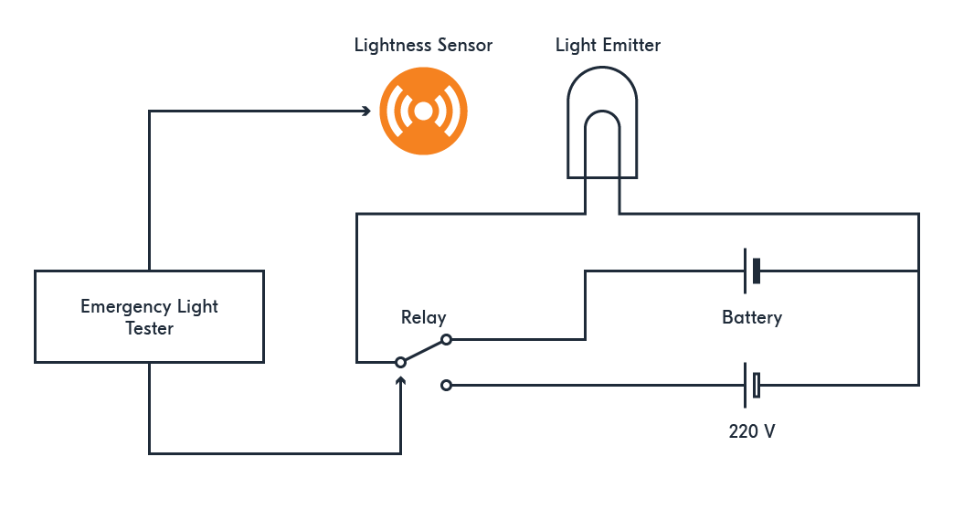
Figure 1: Basic circuit diagram showing how the Emergency Light Tester should be connected to the relay and lightness sensor
The next phase involved defining the communication protocols for the Light Tester. It needed to start a test upon receiving a command, acknowledge this initiation to the Hub to prevent user waiting, and send test results back to the Hub. To enhance user experience, we added the capability to store and retrieve test logs on the Light Tester. This feature is particularly useful in case the Hub loses power or disconnects, eliminating the need for retesting. Additionally, the Light Tester can report current sensor values to the Hub, aiding in diagnostics.
The next step would be to design what messages the Light Tester would have to send and what messages it would need to handle. It needs to have the ability to start a test. This is a message that it will receive from somewhere else, so that is one message that needs to be handled, and it will need to respond to the client with the result of the test. The Light Tester will also need to be able to acknowledge that the test has started; otherwise, the user will wait for hours without getting any response, which would conflict with our goal of having a good user experience. Now, that fulfills the most basic requirements, but as an added convenience, let us add in the functionality of having a log of results stored on the Server to be retrieved. This will be useful if the client loses power or is disconnected for some reason. That way, the user will not have to redo the test and can retrieve the log. Lastly, let us allow the client to retrieve the current value of the sensor, as this will allow the client to check if something is wrong with the sensor.
The Hub
As the primary user interface, the Hub requires access to the data sent by the Light Tester. It must be able to initiate tests, request logs, and retrieve sensor values. An additional function was introduced to verify if a test is in progress, especially if the initial acknowledgment is missed. Given the varying brightness levels of emergency lights, I included a calibration feature for adjusting the threshold values at the Light Tester.
Calibration service
To maintain system integrity, calibration was allocated to a separate mesh model, the Calibration Service. This design choice allows for controlled access, preventing unauthorized calibration by certain clients. The Calibration Service processes calibration requests from the Hub and confirms successful calibration with an 'OK' message.
The final design, depicted in Figure 2, shows each component utilizing mesh for communication. The model handlers manage the messages and specific functionalities like the Test function in the Hub and the UART reader in the Light Tester. The Hub communicates with the user interface externally while the emergency light tester reads the sensor values.
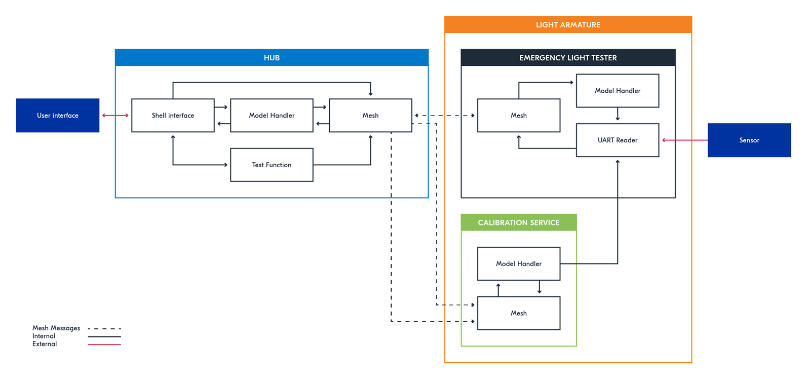
Figure 2: System Diagram
Message Communication Table
The table below outlines the message exchanges between the Hub, Emergency Light Tester, and Calibration Service, indicating which component transmits (TX) or receives (RX) each type of message:
|
Message |
Hub |
Emergency Light Tester |
|
|
Test Start |
TX |
RX |
|
|
Test Run Status |
RX |
TX |
|
|
Status |
RX |
TX |
|
|
Log Entry |
RX |
TX |
|
|
Sensor Value Status |
RX |
TX |
|
|
Get Log |
TX |
RX |
|
|
Test Running |
TX |
RX |
|
|
Calibrate |
TX |
RX |
|
|
RX |
TX |
Figure 3 presents an overview of a small network of these Emergency Lights, illustrating the communication between the armatures and their connection back to the Hub. It details the components of each light armature and the process of transmitting or receiving information within the system. The calibration service and Emergency light tester are depicted as separate entities, yet in practice, they are integrated into a single chip. Thanks to the relay capability of each light armature, they can communicate with the user interface without requiring direct contact.
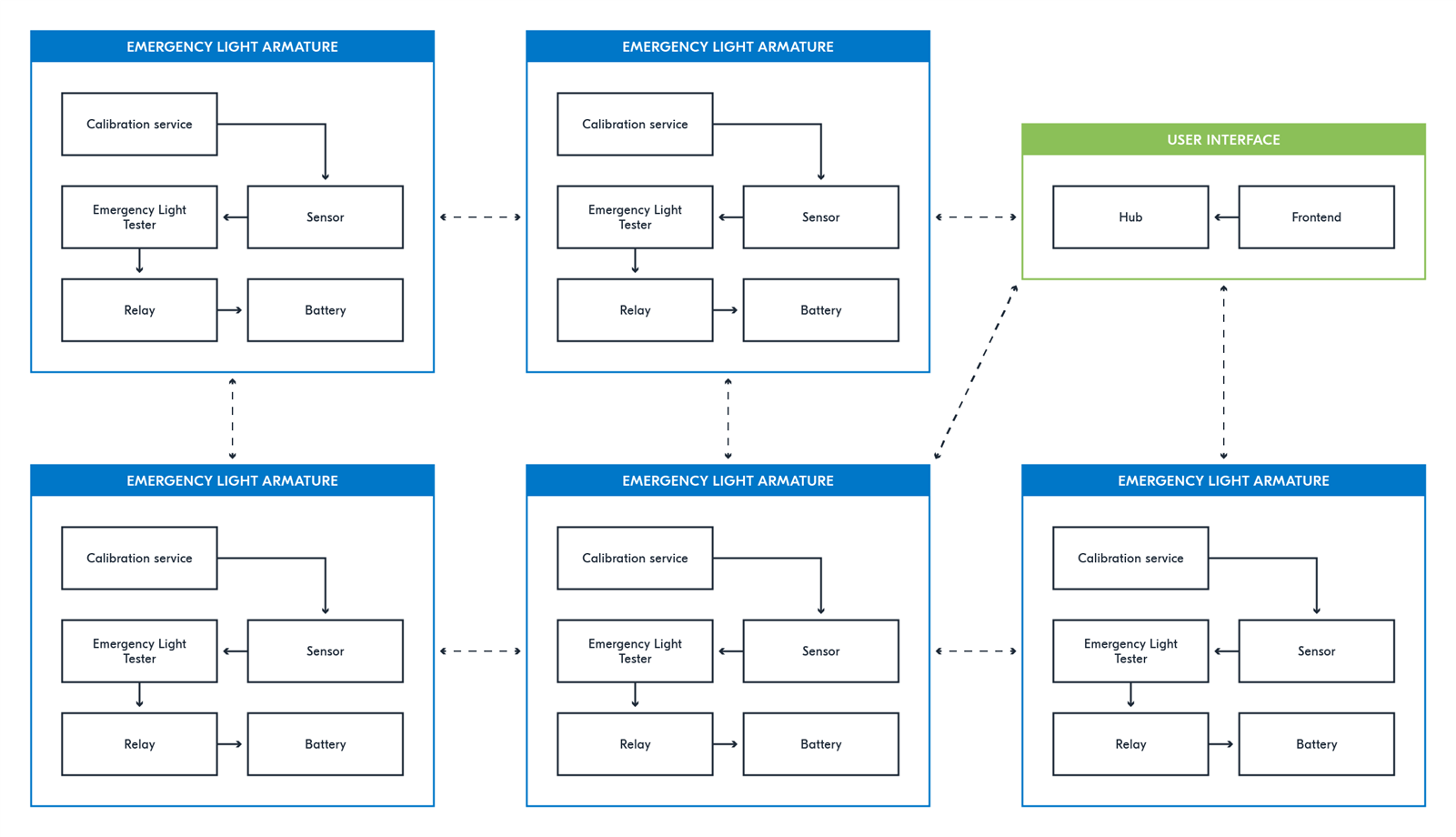
Figure 3: Basic overview of the network of light armatures
Software solution
In developing this system, I started with an existing sample from the nRF Connect SDK, specifically the Bluetooth Mesh: Chat sample, as it is a vendor model that suited my project's mesh network requirements. The project required three models: the server, the light monitor client, and the calibration server. The Emergency Light Armature uses the calibration server and light monitor server on the same device, so only two application files were necessary: light_monitor_srv (Emergency Light Armature) and light_monitor_cli (Hub).
The development steps included:
- Renaming the files.
- Modifying the
vendor_model_id. - Altering the model definitions.
- Implementing the required messages.
- Developing handlers for each message.
- Integrating the light measuring sensors.
- Adding shell support for user interaction.
- Implementing collision handling.
- Creating a simple frontend to give an uncomplicated way to interact with the system
Starting with the chat sample as a base enabled me to bypass the time-intensive initial setup phase of the project, allowing me to dive directly into development. Additionally, the sample's approach to managing the shell interface provided valuable insights, which was particularly helpful when I began integrating shell functionality into my project. This bootstrapped the project quickly, which was important given the time constraints.
Running it yourself
If you want to try this out for yourself, you can find the project on GitHub here: https://github.com/NordicPlayground/devzone-emergency_light_testing.
You will need:
- Two or more nRF52840 Development Kits
- A computer with Python v3.10 and the nRF Connect SDK v2.5.1 installed
- A phone with the nRF Mesh mobile app
- A board compatible ADC brightness-sensor , in this case a light-dependent resistor is used.
- Relay as well as cables to connect them together.
How to setup:
- Clone the project into your mesh samples folder.
- Connect the boards to the computer using a USB cable.
- Build and flash one or more of the boards with the light monitor server and one with the light monitor client.
See here for a guide on how to do so. - Using the nRF Mesh app, provision your boards. Establish a group address for the client to publish to and one for the servers to publish to. Subscribe the client to the servers publish address and the servers to the clients.
See here for a guide on how to do this. - Connect the sensor to pin 03 on the server board, as well as to ground and power.
- Connect the relay to pin 29 on the server board, as well as to ground and power.
- Open the terminal and navigate to where you have the emergency_light_tester.py file.
You have to update the <nameList> variable with the COM ports used by our boards to be able to connect the webserver. They are default set to COM ports used in Linux. You can set all ports you are using, and it will search for the correct one. - This page explains how to install flask and virtual enivironment: https://code.visualstudio.com/docs/python/tutorial-flask
- Activate venv using activate. It can be found in the /venv/bin folder, or you can use the command: (this may be dependent on the OS you are running)
venv/bin/activate
- Run the command
flask --app emergency_light_tester run
(On Windows you may have to use ‘python -m‘ in front of the command.) - Open a web browser and go to the address: http://127.0.0.1:5000/
The web page should now look like the image below, where the names are the address of each Emergency Light Tester. The following functionality is available in the frontend:
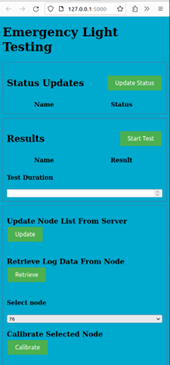
Figure 4: Emergency Light Testing Frontend
Start test
The start test button can be pushed to start a test with the duration set in the Test Duration field. This will start a test on each Emergency Light Tester that is subscribed to the Hubs publish address. The results will show under “Results” where it will show as either “No response” if the Hub is lacking a response from a node, “waiting” if it has received an acknowledge and is waiting for the test result or a “passed”/”failed” once the test has finished. If the Test Duration field left blank the test will run for 120 seconds.
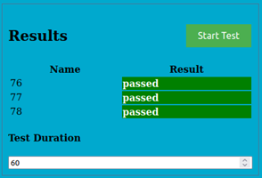
Figure 5: A set of three successful tests that ran for 60 seconds
Update Status
This updates the values in the status field, which is the lightness calculated from the sensor value. This value is only updated when a test is active. Outside of an active test the status will return the last read sensor value.
Update
The update button updates the stored lists of nodes on the Hub. The Hub and the Flask server both keep a locally stored list of nodes registered in the network. The Flask server is updated with the list on the Hub when the server is started, and the Hub is updated with the list on the Flask server when the update button is pushed. The assumption here is that either the Hub or the Local device can be replaced independently and then the full list of nodes can be automatically retrieved.
Retrieve
The retrieve button retrieves the logged results from a node selected in the Select Node field. Results are shown at the bottom of the page, as in figure 4. The results are 1 for passed and 0 for failed.
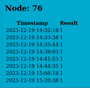
Figure 6: Logged test results for Emergency Light Tester 76
Calibrate
The calibrate button calibrates the threshold value for an Emergency Light Tester in the select node field.
Figure 7 shows an nRF52840 connected to a sensor and relay acting as the Emergency Light tester and a separate nRF52480 acting as the Hub
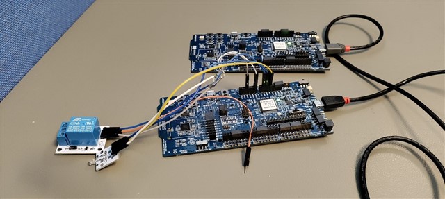
Figure 7: Picture of the set up
Future work
This project, a summer prototype, has ample scope for enhancement. Future improvements could include integration with existing systems for centralized control, mobile device operability, and a refined frontend. For a production version, emergency light bulbs could be manufactured with integrated sensors and chips, either as standalone products or as add-ons to existing fixtures. Automating the system further, with report generation and alert functionalities, could significantly reduce manual oversight. All these focus on creating a system that is simpler to use than today’s systems.
Closing
This blog post demonstrates the ease and accessibility of rapid Bluetooth Mesh project development using the nRF Connect SDK. In about seven weeks, I progressed from a concept to a fully functional prototype, showcasing the potential of such solutions in various applications where reliability, safety, and scalability is crucial. I encourage you to build the system yourself and share any questions or feedback you might have.
References
[1] https://www.regjeringen.no/contentassets/20503ddfe0664fac9e2185c1a6c80716/veiledning-til-byggteknisk-forskrift-tek17_01_07_2017.pdf
[2] https://www.tu.no/artikler/for-darlig-test-av-nodlys/270580

