

Nordic's nPM1300 is a power management IC (PMIC) that is especially well-suited for SoCs like the nRF52 and nRF53 Series. Compared to the SoC's internal regulators, the PMIC is built on a larger 180-nanometer process, increasing efficiency while offering additional features like battery charging and system management features, typically implemented through separate ICs.
In this blog post, we will show how implementing the nPM1300 as a voltage regulator and battery charger can increase the battery life of your application when compared to running directly off of a battery using the internal voltage regulator on an SoC. We will also look at how easy it is to implement USB type-C charging with the nPM1300 and configure it in your project’s software to get it up and running.
Table of Contents
What is a PMIC?
Many SoCs (Systems-on-Chips), including the nRF52 and nRF53 Series from Nordic, can run directly from a rechargeable battery. This is achieved by having an internal regulator inside the SoC that regulates the battery’s voltage to the SoC’s system voltage. Being an SoC means all components inside need to be on the same process node, and for data processing like MCUs or the processor cores of an SoC, smaller means better. However, for power regulation, a smaller process means more leakage currents and a higher cost per transistor, making internal regulators less efficient and unreasonably costly to implement. That is why more and more SoC manufacturers are omitting the internal voltage regulation in their products and instead relying on the user to implement an external regulator or power management IC (PMIC).
Power Management ICs, or PMICs for short, are standalone circuits designed to take power regulation and delivery tasks out of the main application SoC and deal with them separately. PMICs can also include battery charging functionality, a feature rarely found inside SoCs. Instead of inefficient LDOs (Low Dropout Regulators) that convert all excess voltage into heat, a PMIC will most likely use a switching regulator. A step-down regulator is most suitable for converting power from battery voltage to the SoCs system voltage, also known as a BUCK. This switches the voltage on and off with a specific duty cycle to produce the correct voltage, and then it uses an LC filter to smooth out the square wave back to a proper DC voltage. This is achieved more efficiently and cheaper with a larger process than what we typically find in modern processing hardware, like SoCs or MCUs. As an example, the nPM1300 PMIC, which we will have a closer look at in this blog post, is built on the 180-nanometer process.
How to choose a PMIC for your design
To choose what PMIC is suitable for your design, you need to make some considerations:
How many power rails does my system require?
Sometimes, all the components of your solution can be powered by the same power rail. This requires that all the components can operate from the same voltage and that the current consumption of all the components doesn’t exceed the current delivery capabilities of the regulator for this rail. If your components need different voltages to operate, using two separate power rails of the PMIC can be more efficient than having an external regulator or voltage dividers. Using different power rails also ensures stability, as one sub-system should not affect another sub-system if it exceeds its expected current limit.
What is the maximum current load the system can be expected to draw?
Obviously, the PMIC needs to be able to deliver the current of all the components you’re powering from it. This can sometimes be hard to calculate. The safest route is to read the spec sheets and always dimension for the absolute biggest load any component can present. This leads to vastly over-dimensioned power delivery subsystems. A better way is to measure the peak currents of your specific application when running on the hardware and design the power delivery subsystem to be within the max current draw of the system, plus a safety margin of [spuriously chosen value] percent. This is not always an option, as you must build the solution before you can measure its current draws. The best while still practical option, at least for Nordic SoCs, is to use our online power profilers. Here, you can input the radio settings of your application and get an estimation of the power requirements of the SoC. The radio settings are essential, as the radio tends to be the most current consuming part in wireless SoCs.
Which additional features do I need?
Depending on what type of device you’re making, you might need to take design considerations regarding power delivery that is not as straightforward as just input and output of the correct voltages and currents. For example, consider a device with a non-removable battery, either for IP rating or to make the device as small as possible. For users of this device, having a non-removable battery poses one main challenge: what to do if the device locks up. Buttons are usually implemented through software, which obviously becomes unresponsive in such an event, and hardware power switches are rare in modern devices. Normally, you would simply unplug the battery to force a power cycle. This is not an option with a non-removable battery, so you must implement some sort of hard reset switch. A hard reset switch can be implemented as a standalone IC that has this as its only function or through a PMIC with this as an additional system management feature.
Other features you might wish to implement in your power management subsystem are things like fuel gauge ICs, external watchdogs, and hibernate timers. These are all features that are normally implemented by adding dedicated “supervisor ICs”. With the nPM1300, however, you don’t have to because they are all integrated directly into the PMIC.
How to bypass internal regulators for higher efficiency
When you have chosen your PMIC, you’re ready to start designing your power management sub-system. The first step here is to make sure you operate at the maximum efficiency your system is capable of. A fully charged lithium battery can have a max voltage of up to 4.25 V, many SoCs however can not operate at such high voltages, because the processing cores inside need very specific voltages. To ensure the correct voltage for the processor, SoCs almost always include a regulator for this final step allowing for a range of voltages to power the SoC. In addition to this, many also include an extra regulator step to be able to allow the SoCs to be run from a battery or USB power source without external regulators. This internal regulator is built on the same small process node as the rest of the SoC, which makes it less efficient than regulators built on a bigger process.
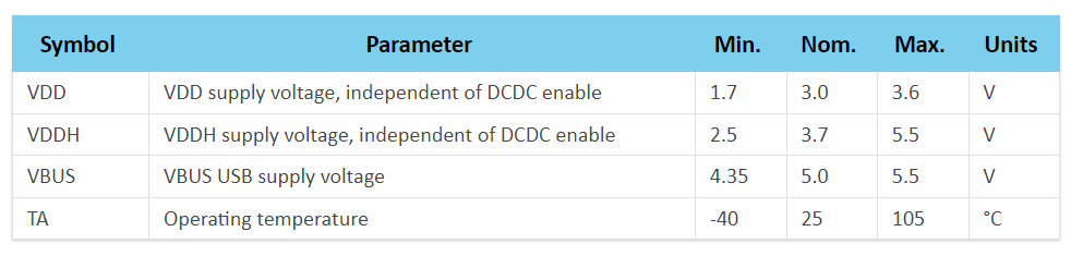
As an example, the nRF5340 SoC has a maximum operating voltage of 3.6 V, so to run directly from a battery there needs to be an additional regulator before the voltage input (VDD) of the SoC. The separate VDDH input includes this additional first regulator, stepping down the voltage to a value within the acceptable range for VDD, which in turn supplies the SoC.
Facsimile of the online documentation for the nRF5340 SoC on infocenter.nordicsemi.com
Bypassing this initial regulator and replacing it with an external one would increase efficiency. As an example, the buck regulators in the nPM Family products are much more efficient than the first regulator step of the nRF5340’s VDDH, partially due to their larger process nodes. This also means that you can run the nRF5340 at a voltage closer to the optimal voltage for the processor, ensuring the highest possible performance and efficiency. In practice, the method of bypassing it is simply connecting your power source directly to a VDD pin on the SoC instead of the VDDH pin required for direct battery operation.
Effects of bypassing the regulator
We have done measurements on an nRF5340 powered by a battery directly and with an nPM1100 PMIC, which uses the same process node as the nPM1300. In two different scenarios with the same small lithium battery, we see that the latter gives an efficiency gain that can increase the battery life by more than 20 %.
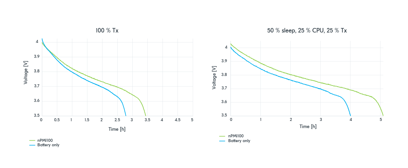
We see that in both scenarios the time it takes for the battery to drop below 3.5 V is over 20 % longer for both systems when using an external PMIC as opposed to when using the internal VDDH regulator.
Implement USB-C charging
Micro-USB type B connectors have long been the standard for charging small devices. Understandably why, since connecting this type of USB connector is super simple. You can expect 5 V to be delivered with two connections in your layout, no questions asked. The new standard of USB-C is a little more complicated. As the USB-C connector is rotationally symmetrical, you need twice the connections to ensure that any USB-C cable will power your device correctly. In addition, USB-C offers a multitude of voltages and current limits and has a cable with the same connector at both ends. For the sake of simplicity, let’s assume we’re designing a device that does not communicate over USB and only uses it for charging. This device must negotiate with the device at the other end to determine which is supposed to deliver power to which. One way of doing this is to use a dedicated IC, also known as an “E-mark chip”. The E-mark chip connects to the two CC-pins on the USB-C connector and handles this negotiation, letting the source and sink devices agree on which is which. These are so small that some even make USB-C to non-USB power cables and include the e-mark chip in the cable, allowing the cable to request specific voltages like 12 V directly from any high-quality USB-C source.

Image source: Chindi.ap (Wikimedia Commons)
The alternative to this is bootstrapping, grounding the CC-pins on the receptacle through resistors, which makes this USB-C port emulate a USB type-B port. The downside of bootstrapping is that you’re limited to the same current draw for the entire system, as with USB type-B charging. This will severely limit your charging speed, especially if the device is on and powered through the USB at the same time as charging.
The third and best option is to use a PMIC like the nPM1300, which has the functionality built in. Simply connect the nPM1300’s CC-pins to the USB-C receptacle’s CC-pins, and you’re done. This allows the nPM1300 to achieve its full potential of 800 mA battery charging when connected to a compatible USB-C source and powering the bucks and LDOs simultaneously.
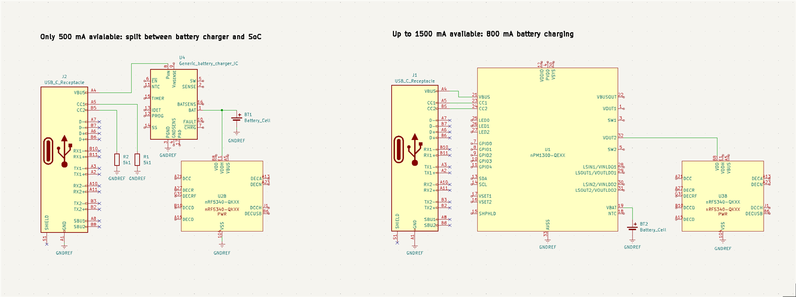
Note that these are simplified diagrams for illustrative purposes, where most passive components and all data lines are omitted, and only the power domain of the nRF5340 is shown. For actual schematic and layout work, please follow the proper reference designs.
Configure the nPM1300 in software
As most PMICs do not feature internal processors or memory, configurations are normally done via I2C-compatible two-wire interfaces (TWI). Enabling and disabling features are done by setting the correct bits in the correct registers, corresponding to the product spec or datasheet. This requires the user to enable TWI on their SoC or other host device, physically connect the SCL and SDAs, and send the correct values to the correct registers’ TWI addresses on the PMIC As an example, the TWI address for the nPM1300 is 110 1011 or 0x6b in hex. From the product spec we find that the register for controlling BUCK1 is offset by 0x400. So to enable software control of BUCK1, you would write the value of 1 to this register with an additional offset of 0x0F, also found in the product spec. The register for setting the voltage has the additional offset of 0x08, so to set BUCK1 to output 3 V, you would send the value 20 (0x14 in hex, the register value corresponding to 3 V, according to the product spec), to 0x408. This is a tiresome way to enable features that require a lot of time browsing datasheets to find the right registers, interpret their functionality, and set them accordingly.
If you’re lucky, someone might have written a driver for this in the RTOS you’re working with. The driver handles all the TWI communication, and all you must do is figure out what functions to use and the correct arguments to pass it for calling the functionality. This is also the case for the nPM1300, which has drivers for it included in Zephyr. The easiest way of taking advantage of these drivers is to add the nPM1300 EK shield to your application. The label for the nPM1300’s BUCK1 is npm1300_ek_buck1, and the function for setting the voltage is “regulator_set_voltage”, with the buck and the min and max allowed voltages given in microvolts as arguments. This makes the example code slightly shorter but also requires you to dig through the documentation or the code of the drivers themselves to find the correct functions and arguments.
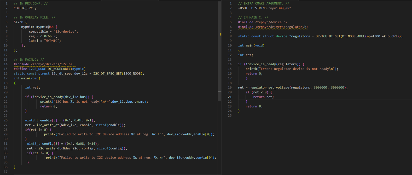
Two examples of non-ideal ways of enabling BUCK1 through writing TWI messages to PMIC
Introducing nPM PowerUP: With nPM PowerUP, all the functionality of the nPM1300 PMIC is configurable through a user-friendly GUI. Selecting the output voltage is as easy as setting the slider to the desired voltage or punching in the number if you prefer. Then, click the “export configuration” button in the top left corner.
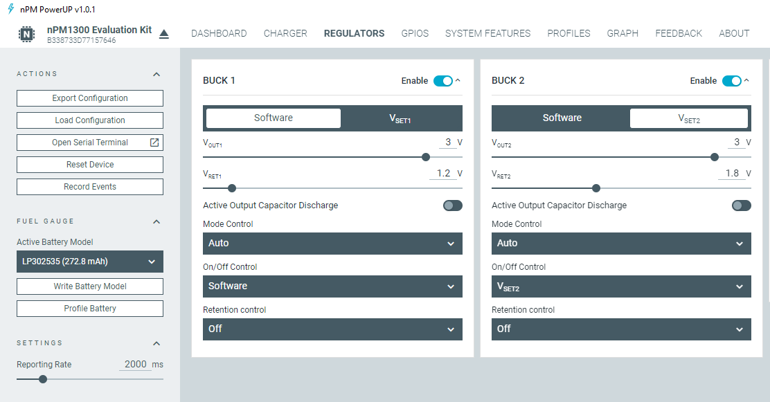
Screenshot of the nPM PowerUP application found inside nRF Connect for Desktop
The output generated from the nPM PowerUP app takes the form of a devicetree overlay file. When you include this overlay in your project, it pulls in the Zephyr TWI-driver (“I2C”) and the drivers for the specific features of the nPM1300 you have configured in the GUI. This means that the automatically generated overlay uses the same amount of memory as if you’re using the drivers manually, like in the second code example. It also initializes all the functions controlled by these drivers to the value you selected in nPM PowerUP before exporting.
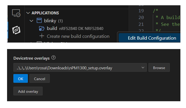
To implement this devicetree overlay file, you click the “edit build configuration” in nRF Connect for VS Code extension and then add the overlay file through the “Add overlay” button found under “Devicetree overlays”.
You must also make sure your prj.conf includes these configs:
CONFIG_GPIO=y
CONFIG_SHELL=y
CONFIG_LOG=y
CONFIG_REGULATOR=y
CONFIG_SENSOR=y
CONFIG_LED=y
This pulls in the relevant configs from the nRF Connect SDK into your project, enabling the drivers for the different features of the nPM1300, and also enabling logging and the shell module. The shell module allows you to take advantage of a predefined command set that is created specifically for the nPM1300.
If you’re using a sample application that does not utilize TWI by default, you also need to add the following lines at the end of your overlay:
&i2c0_default {
    group2 {
        psels = <NRF_PSEL(TWIM_SCL, 0, 27)>, <NRF_PSEL(TWIM_SDA, 0, 26)>;
        bias-pull-up;
        };
    };
/delete-node/ &{/pin-controller/i2c0_default/group1/};
This enables the internal pullups for the I2C lines, where the values 27 and 26 specify the pin numbers of the SDA and the SCL pins on the SoC used for this example. This internal pullup allows you to omit external pullup resistors on the I2C lines in your hardware layout.
Closing
Adding a PMIC increases your system's power efficiency when compared to the same system supplied directly by a battery through the SoC’s integrated regulators. In addition, some PMICs, like the nPM1300, feature additional useful and often necessary functionality usually implemented by adding dedicated “supervisor ICs” in the power management subsystem. Implementing all of these features, as well as setting up the SoCs firmware to the core functionality of the PMIC at startup, is quite easy to do when using the nPM PowerUP app as a configuration GUI and exporting the settings into an nRF Connect SDK project through a generated devicetree overlay file.

