

One of most frequently asked question from customers is howt to test RF to evaluate RF performance on their device. The precondition of this is to connect UART between PC and DUT(Device Under Test) prior to execute 'RF Test example' included in the SDK. However, there are always small issues for wiring, misconnections(TxD, RxD, cross or parallel) and assigning available Pins for UART, baud rate and so on..
Here I suggest one option to send command wirelessly using Gazell from dongle instead of UART.
Below connection is traditional environment for the RF test.
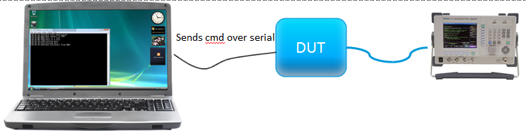
<Pig1. traditional way for RF test>
And below one is another possible way for the same test.
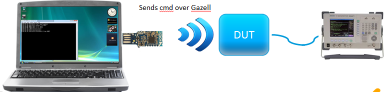
<Pig2. new pissible way for RF test>
Dongle keeps set command and parameters until DUT is powered and sends ready signal. The application on dongle side needs extended codes for Gazell in addition to original codes.Please refer the attached this file main_dongle.c . This is not so optimized, but it basically works fine. Like traditional way, user can set each parameters and commands and then wait for the DUT. The application on device is inherited from Gazell Device example included Nordic Proprietary protocols in the SDK. As you know, this example is used as a counterpart for receiving the data. So once this device sends ready signal to host(dongle) being powered on, the dongle sends the command with parameters. Relevant codes are attached main_device_rf_test.c .
Supposing the binary is flashed to dongle and connected to PC and the device is flashed and power off, here is the detail description step by step.
Step 1. Execute console like Tera term to communicate between PC and dongle. I instanced Tx constant carrier for example as below capture.
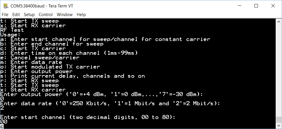
<Pic 3. command on PC to dongle and waiting>
As you can see, the dongle got the data and waits for DUT to be powered and send ready signal.
Step 2. Power on the DUT(Please make sure the DUT is already connected to spectrum analyzer for conduction test) and then you can see one more log, 'Host sent command to DUT..' at the end of the line as below.
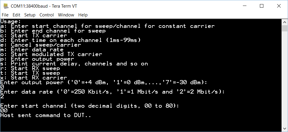
<Pic 4. dongle sent command to the DUT>
Step 3. Once the DUT is connected to the equipment enough to see waveform, you could see as below
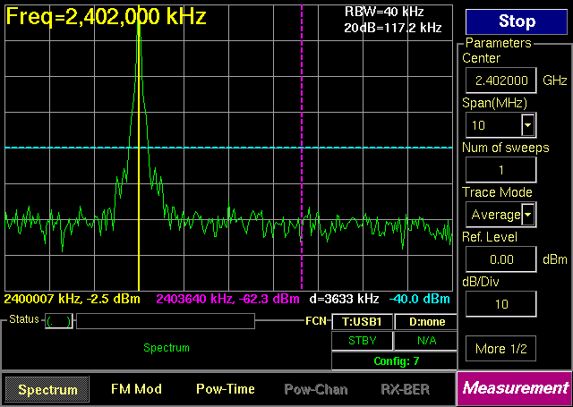
<Pic 5. capture screen from spectrum analyzer>
I tested TXCC(Tx constant carrier) and TXMC(Tx Modulated carrier) and confirmed it worked exactly same as original way(UART command). For the other parts like TXSWEEP and RX, it can be easily added with the same way. One more thing for the codes on devices side, the transmitted data is stored to flash memory and then reset to show the waveform. It's because Gazell can affect collision to show pure RF performance. The tested SDK is based on SDK10.0 and the test equipment is TC3000C by TESCOM.
Any feedback is welcomed and hope it would be helpful.!
