

Overview
In this blog, you will measure the PSM floor current for the rev. 2 version of the nRF9160 SiP.
Requirements
Hardware
You will need:
- an nRF9160-DK (the one used here was v1.0.0). Be sure that your version uses rev2 of the nRF9160 SiP (v0.15.0 or later)
- an activated SIM card (the iBasis card that comes with the DK was used here). If you have a carrier SIM, it will likely a provide faster switch to PSM mode than an MVNO SIM
NOTE: When running the asset tracker example for the first time, you must add your device to the nRF Cloud and activate your SIM card as described in the instructions. Otherwise, the DK will not connect to the cloud, even if it attaches to LTE network - a Power Profiler Kit II (the one used here was v1.0.1)
Software
Install nRF Connect for Desktop to your desktop, then run the tool and install the following apps:
Make sure that you have the NCS toolchain and SDK installation completed as covered in the nRF Connect for Desktop Toolchain Manager. This blog used NCS version 1.5.0
Update the nRF9160 Modem Firmware
If you already have the latest modem firmware installed, you can skip to the next section. Otherwise, download the latest modem firmware version from here to your desktop and do not unzip it. Version 1.2.3 was used in this blog. Ultimately, you will need to program your nRF9160 modem with firmware compatible with your carrier
1) Make sure that your nRF9160-DK is plugged into your PC with a micro-USB cable and that the DK power switch is on.
2) Run nRF Connect for Desktop and then open the Programmer app.
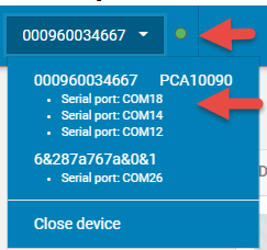
3) Click Select device in the upper-left of the Programmer app and select your PCA10090 (the three serial ports shown are a single selection). The indicator to the right will go green.
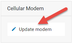
4) Click Update modem in the lower-right. Browse to your desktop and select the mfw_nrf9160_1.2.3.zip file (or later).
5) Click Write.
6) When the process completes, press the Close button.
7) If you have the asset tracker application installed, press the reset button on your DK to restart the application. LED3 will start blinking, indicating that the nRF9160 is scanning for a network connection. When LED4 lights, the connection to nRF Cloud has been made.
8) Close the nRF Connect Programmer.
Setting up the PPK II and DK in Source Meter Mode
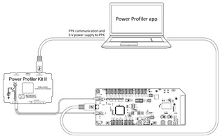
On the nRF9160-DK, it is easy to directly power the nRF9160 SiP (VDD_nRF pin on the DK) and isolate it from rest of the board. This allows current measurements to be performed with a power analyzer on the nRF9160 alone.
Some tips for using the PPK II:
- Connect it directly to your computer, preferably with a short USB cable. Do not connect through a USB hub or docking station as this may introduce additional noise.
- Use source meter mode instead of ampere meter mode for very low current measurements.
1) Remove and save the jumper on P22 of the nRF9160-DK.
2) Connect the USB DATA/POWER connector on the PPK II to your PC with a micro-USB cable. Assure that the PPK II power switch is on. The PPK II will blink green.
3) Insert the 4 pin cable that came with the PPK II into the 4-pin power connection on the PPK II
4) Connect PPK2 VIN (the connector can be plugged into the PPK in either direction, so this wire may be brown or red) to P22 VDD_nRF (the pin nearest the Debug_out connector)
5) Connect PPK2 GND (black wire) to P21 GND (marked - and nearest the USB connector)
6) Connect the USB connector of the nRF9160-DK to your PC with a micro-USB cable
7) Assure that your DK’s power switch is turned on. You will see the LED near the large Segger debugger chip flash indicating that it is powered, but the nRF9160 itself is not powered at this time.
Setting up the Power Profiler App
In nRF Connect for Desktop, Open the Power Profiler app.
1) On the upper-left, click the SELECT DEVICE button. Click your PPK2 to connect. If you are notified that the device must be programmed, click Yes ... the PPK II will glow red when programming. The PPK II will glow blue when connected.
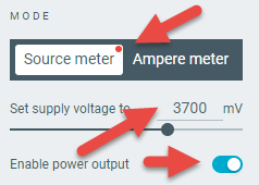
2) Under MODE on the left, click the Source Meter button
3) Underneath the MODE selection, set the supply voltage to 3700mV
4) Click the Enable power output selector to switch on power to the nRF9160. Note that LED3 is now blinking, indicating that the nRF9160 is powered and the asset tracker application is running.
PSM Connection with Logging
Now that the PPK II and the DK are ready to go, we can test the udp sample. Documentation on the udp sample can be found here.. Logging is enabled in the code so that we can see its status. We'll turn logging off later to lower the current.
1) In Windows Explorer (or other), browse to ...\v1.5.0\nrf\samples\nrf9160\udp. Open prj.conf for editing.
2) At about line 11, find the line containing CONFIG_SERIAL=n. Change it to CONFIG_SERIAL=y This will enable logging so that we can see that the code is operational. We will disable logging afterwards to reduce current.
3) At about line 37 find the line containing CONFIG_LTE_PSM_REQ_RPTAU="00100001". Change it to CONFIG_LTE_PSM_REQ_RPTAU="00100100" in order to connect in PSM mode with a 4 hour TAU. Save your changes and close the editor.
4) Make sure that the nRF9160 is powered via the Power Profiler's Enable power output switch (shown above).
5) Open a command window in ...\v1.5.0\nrf\samples\nrf9160\udp. Type nrfjprog -e and press Enter to erase the nRF9160 application flash.
6) When the process completes, type west build -p -b nrf9160dk_nrf9160ns to build the project. Press Enter.
7) When the process completes, type west flash to program the project into the nRF9160's flash memory. Press Enter.
8) When the process completes, open nRF Connect for Desktop and run the LTE Link Monitor app. Connect the app to your nRF9160-DK. Note the time and press the reset button on the DK. Watch the terminal output in LTE Link Monitor and note the amount of time until you see PSMTransmitting UDP/IP payload... This may take a few seconds for a carrier SIM to a few minutes for an MVNO SIM. If you see TAU: -1, the carrier did not accept the switch to PSM mode. Press reset to try again. If you see TAU: 14400, the carrier accepted the switch.
9) Close the LTE Link Monitor.
Measuring PSM Floor Current with Logging Disabled
In order to measure the lowest possible current, logging must be disabled.
1) In Windows Explorer (or other), browse to ...\v1.5.0\nrf\samples\nrf9160\udp. Open prj.conf for editing.
2) At about line 11, find the line containing CONFIG_SERIAL=y. Change it to CONFIG_SERIAL=n. Save your changes and close the editor.
3) Make sure that the nRF9160 is powered via the Power Profiler's Enable power output switch (shown above).
4) Open a command window in ...\v1.5.0\nrf\samples\nrf9160\udp. Type nrfjprog -e and press Enter to erase the nRF9160 application flash.
5) When the process completes, type west build -p -b nrf9160dk_nrf9160ns to build the project. Press Enter.
6) When the process completes, type west flash to program the project into the nRF9160's flash memory. Press Enter.
7) Back in the Power Profiler, press the Start button to begin logging the nRF9160 current. Press the reset button on the DK and wait the amount of time that you determined in step 8 above.
8) Click the 10s button at the top of the Power Profiler display to set the time window to 10 seconds. Your display should look like the below.
9) Press the Stop button to stop recording.
10) Use Shift and Left mouse click to drag a measurement window across the display like that shown below. Note the measurements in the SELECTION pane.
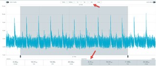
The 1Hz spikes are caused by the nRF9160's DCDC refresh circuit. The higher frequency component is noise. The average current measured is 3.3uA.
Summary
PSM sleep current is easily measurable on the nRF9160-DK at 3.3µA.
Note that the nRF9160 also powers the SIM card, and using this setup, SIM current will be included in the measurement. However, in this case, because of the extended sleep time allowed by PSM mode (and in general for eDRX/PSM larger than a certain limit), the nRF9160 automatically shuts down the SIM card (the SIM must support this feature) . In most cases, the current contribution of the SIM is zero and is not visible in the current measurement. Some SIM cards do not permit shutdown, however and the current will be visible.

-
$core_v2_ui.GetResizedImageHtml($comment.User.AvatarUrl, 44, 44, "%{border='0px', alt=$comment.User.DisplayName, ResizeMethod='ZoomAndCrop'}")
$core_v2_ui.UserPresence($comment.User.Id)
$comment.User.DisplayName
-
Cancel
-
Vote Up
$currentVotes.ToString("+0;-0;0")
Vote Down
-
$core_v2_ui.Like($comment.CommentId, $comment.CommentContentTypeId, "%{ Format = $likeFormat, IncludeTip = 'true' }")
-
Sign in to reply
-
More
-
Cancel
Children