

NFC principle
A NFC system consists of two devices, an active and a passive device. The active device is powered, and induces a magnetic field with a coil inductor antenna. When the passive device is placed in this magnetic field, the varying magnetic field will induce current (power) in the passive device. The induced power in the passive device is used to retrieve and transmit data back to the active device. A NFC antenna is a coil inductor and together with capacitors to ground, they form a parallel resonant LC tank. A maximized power transfer takes place when the active and the passive device have the same resonant frequency. Since the active device operates at 13.56 MHz, the passive device should also resonate at that frequency. In addition to the resonant frequency, the antenna size and shape do also matter. Two similar antennas will result in more power transfer than two very different antennas. An active device can also be called a poller, and a passive device can also be called a listener or a tag. The nRF52 is a NFC tag device.
Tuning goal
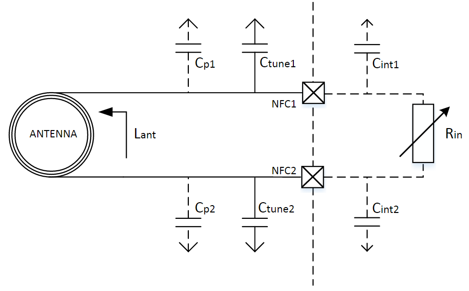
Referring to the equivalent circuit below, the antenna and the parallel capacitors form a LC-circuit. The goal of the tuning is to find the value of the parallel capacitors, C_tune1and C_tune2, so that the resonance frequency of the LC-circuit is at approximately 13.56 MHz.
Tuning
Estimation of values Before starting the tuning, it is a good idea to calculate an approximate value of C_tune1 and C_tune2, especially of using the tuning method of varying the frequency. Note that C_tune1 and C_tune2 should have the same value.
Estimation of C_tune1 and C_tune2:
-
Find an approximate inductance, L, of the NFC tag antenna using an appropriate method:
- Find its value in its datasheet
- Calculate the inductance based on its dimensions. That can be done using an online calculator.
-
Based on the calculated inductance of the NFC antenna, the values of the parallel capacitors can be calculated using the below formula from the [NFCT antenna recommendations chapter in the nRF52832 Product Specification](http://infocenter.nordicsemi.com/index.jsp?topic=%2Fcom.nordic.infocenter.nrf52832.ps.v1.0%2Fnfc.html&cp=1_2_0_40_8&anchor=concept_ryw_4hk_1s). C_tune1 and C_tune2 should have the same value. C_int is approximately 4 pF.
C_tune1, C_tune2, and the resonance frequency:
If using the tuning method with the network analyzer, the following may be useful: if the resonant frequency is lower than 13.56 MHz, the value of C_tune1 and C_tune2 should be decreased. If the resonant frequency is higher than 13.56 MHz, the value of C_tune1 and C_tune2 should be increased.
Configuration of the chip:
In order to do the tuning with varying the frequency, the NFC module in the nRF52 has to be enabled, and the internal variable resistor R_in has to be set to a fixed value. It consists of running the following commands:
Nfc_settings.bat for nRF52832:
nrfjprog -f NRF52 --memwr 0x40005668 --val 15
nrfjprog -f NRF52 --memwr 0x40005650 --val 4
nrfjprog -f NRF52 --memwr 0x40005000 --val 1
Nfc_settings.bat for nRF52840:
nrfjprog -f NRF52 --memwr 0x4000568C --val 0x38D48
nrfjprog -f NRF52 --memwr 0x40005000 --val 1
Note 2: The voltage between the pins NFC1/2 on nRF52 and ground should be the following when the NFC module is enabled and disabled:
Voltage:
NFC module enabled (TASKS_ACTIVE): Approximately 0 V
NFC module disabled (TASKS_DISABLE): Approximately VDD/2
Tuning methods
Network analyzer:
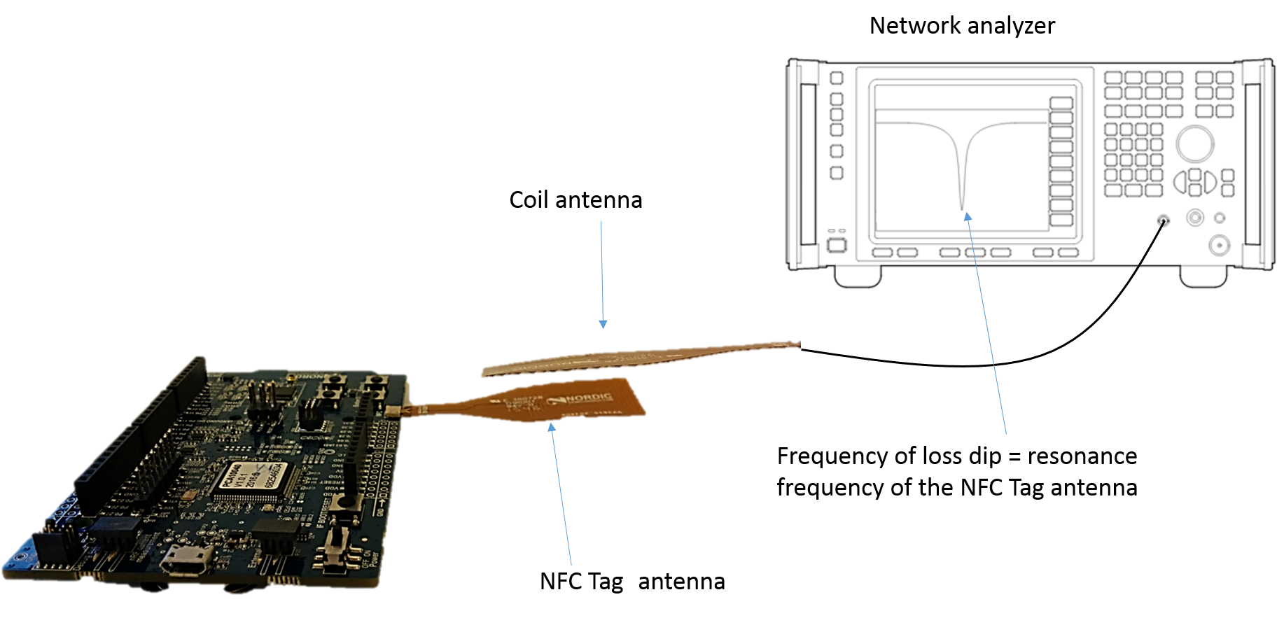
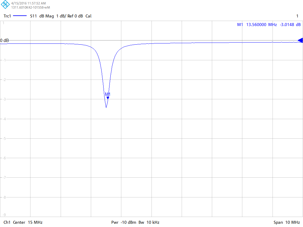
Principle: Connect a coil antenna, with a size similar to the NFC antenna, to a network analyzer. The network analyzer should power the antenna slightly, with for example -10 dBm. Set the coil antenna in a distance of 1-2 cm of the NFC antenna. Use the network analyzer (S11, dB Magnitude) to measure loss in the coil antenna over a frequency span, for example 10 – 15 MHz. The frequency that results in a dip is the resonance frequency of the NFC tag antenna. Change the value of C_tune1 and C_tune2 according to section 4.2 in order to change the resonant frequency of the NFC tag antenna. When using this method, the nRF52 chip does not need to be powered.
Required equipment:
- Network analyzer*
- Coil antenna, for example a metal wire in a coil
- NFC tag antenna connected to the board with nRF52
*Requirements for the network analyzer: one port, low frequency range (needs to cover 13.56 MHz).
Setup:
-
Connect the coil antenna to a network analyzer and the NFC tag antenna to the nRF52 device.
-
Measure the resonance frequency of the NFC tag antenna: Increase the value of C_tune1 and C_tune2 to lower the resonant frequency and vice versa.
Method of varying the frequency:
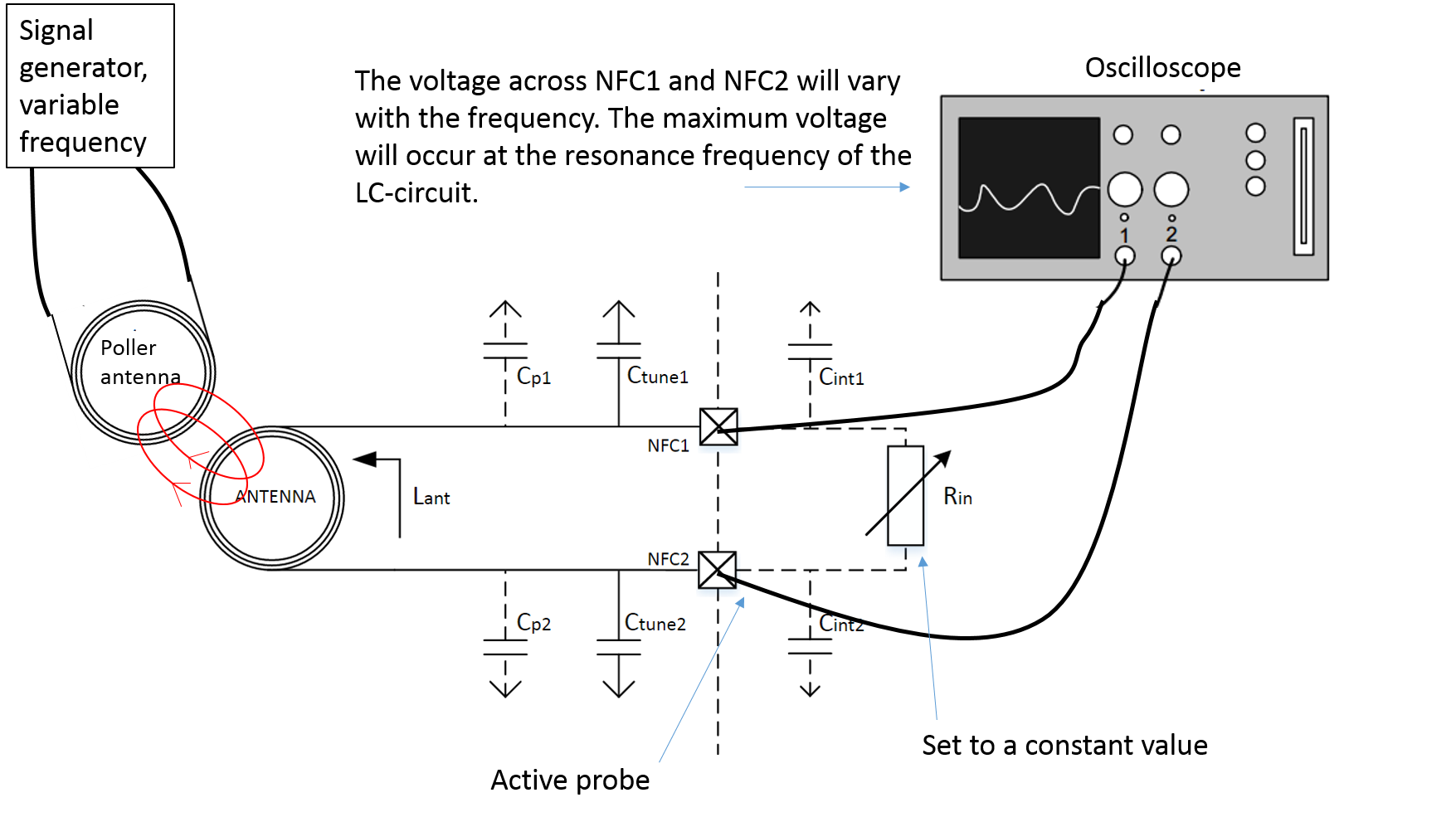
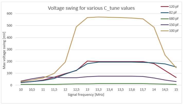
Principle and how to do it: For given a given value of C_tune1, C_tune2, and R_in , vary the frequency using a signal generator (13 - 14 MHz) and measure the maximum voltage swing using an oscilloscope. Measure the voltage swing of a set of C_tune values. The value of C_tune1 and C_tune2 that results in the largest voltage swing in the frequency region of approximately 13-14 MHz, will be best value among the tested ones for that antenna. It means that the value of C_tune1 and C_tune2 with the largest voltage swing will be the value that results in a LC circuit with resonance frequency closest to 13.56 MHz, among the tested values.
Note 1 – setup of the chip: When doing the measurements, it is important that the variable internal R_in is set to a fixed value, see “nfc_settings.bat”.
Note 2 – accuracy of the results: In order to obtain accurate/useful results, the distance and relative placement between the poller antenna and NFC-tag antenna have to be exactly the same for all measurements. A slightly change of distance or relative placement may change the maximum voltage swing considerably, and hence change the validity/accuracy of the results.
Required equipment:
-
Signal generator that can generate signals up to at least 14 MHz.
-
NFC antenna with resonant frequency of 13.56 MHz (the poller antenna in the figure below)
-
Oscilloscope
-
Active probes
Active probes are required in order to minimize the capacitance between the NFC antenna and the oscilloscope. The reason that active probes are required is that they have much less capacitance than passive probes.
Steps:
- Calculate an approximate value for C_tune1 and C_tune2, like described in section 4.1.
- Create a good setup for the poller and tag antennas that will make the distance and relative placement between the antennas constant for all measurements. Any change in distance/placement will lead to inaccurate measurements.
- Set the internal R_in in nRF52 to a fixed value using nfc_settings.bat
- Measure the maximum voltage swing in the frequency region 13 – 14 MHz for a set of C_tune values.
- Select the value of C_tune1 and C_tune2: choose the value of C_tune1 and C_tune2 that results in the largest voltage swing.
Considerations
Choice of antenna (antenna size and shape):
Maximum power transfer occurs when the NFC tag and NFC poller antenna have the same shape and size. Therefore, in order to achieve the best performance, the choice of NFC tag antenna should be made based on the application and the typical poller NFC antenna for that application. It could be a good idea to test the NFC tag with many readers.
Choice of tuning method:
The method using the network analyzer is the preferred method because there are less sources of error, and the network analyzer “outputs” actual results; for a given measurement the network analyzer shows the resonant frequency for the tag antenna. The other method, use an oscilloscope to measure the maximum voltage swing, has more sources of errors and “outputs” relative
If you have any questions/feedback, please leave a comment below.

