PDM stands for pulse density modulation.
PDM is a form of modulation used to represent an analog signal with a binary signal. In a PDM signal, specific amplitude values are not encoded into codewords of pulses of different weight as they would be in pulse-code modulation (PCM).
Currently, PDM is a very popular and low-cost solution particular into mobile telephones.
The detail specification on the nRF52832 can be found at the infocenter.
In this example, we would like to show how to use the PDM interface on the nRF52832 to record and convert to the PCM format. And then, it would store inside the internal flash.
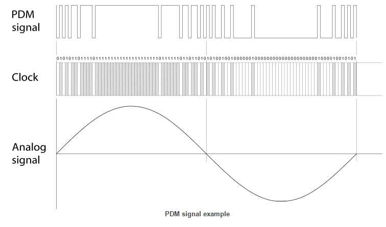
Example of PDM data
Digital microphone interface
The digital microphone is interfaced using a digital pulse-density modulated (PDM) signal. The PDM interface consists of two IOs:
- Clock (MIC_CLK)
- Data (MIC_DOUT)
The figure below illustrates the PDM interface signals. Note that the clock signal frequency is significantly higher than the analog signal frequency.
PDM on nRF52832
A PDM microphone is connected to the nRF52 DK board.
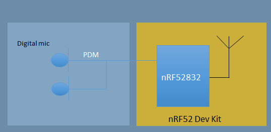
We use the PDM driver which is provided from Nordic nRF5x SDK.
PDM initialization
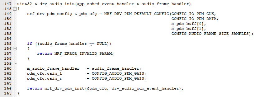
where CONFIG_AUDIO_FRAME_SIZE_SAMPLES is 64.
The PCM data would be stored into the DMA RAM buffer (p_pdm_buffer).
Store the PCM into the internal flash by using the Pstorage RAW module.
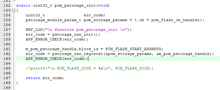
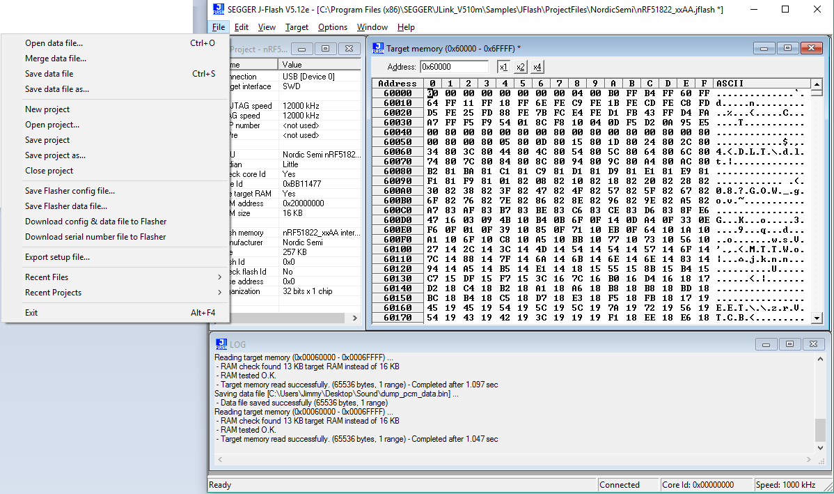
The PCM data would be stored at the flash region between 0x60000 and 0x70000 in this example code.
Using the Segger J-Flash to dump the PCM data out.
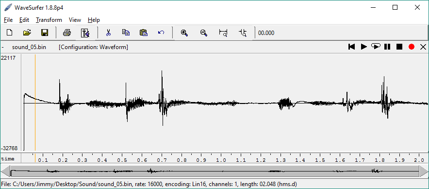
And play as below,
Note:
-
The first few samples (typically around 50) might hence contain invalid values or transients. It is therefore advised to discard the first few samples after a PDM start.
-
No BLE activity during the PDM recording (stop the BLE advertising)
Requirements
- nRF52 SDK version 11.0.0
- nRF52832 DK 1.1.0 or later
The project may need modifications to work with other versions or other boards.
To compile it, in the nRF5_SDK_11.0.0_89a8197\examples\ble_peripheral folder.
Any feedback is welcome and hope it would be helpful!


Top Comments