

Written by Kaja Koren, Lena Haraldseid, Halvor Bjørstad, Martin Moldsvor & Magnus Stentsøe
The summer students in Nordic's application group spent this summer developing an interactive game using Nordic hardware, to demonstrate combining short-range connectivity with the nRF52840 DKs and cellular connectivity using the nRF9160 DK. The game is similar to capture the flag, where each of the two teams configures actions on robots (an nRF52840 DK) with the goal of crossing the finish line first.
If you're interested in recreating this project, you will find the source code for all components at the bottom of this page.
Table of Contents
Why does Nordic pay students to work on a game?!
Each summer Nordic employs many students to work full-time on various projects. One of the many reasons for this is to put Nordic technology in the hands of engineers that do not work with it every day. This is called dog-fooding, and it is a way to scrutinize the solutions and ensure that they can be understood by users who do not have many years of experience working with it. The application group, where we were summer students this year, serves as Nordic’s internal customer and is responsible for developing tools like development kits, application samples and cloud solutions that help customers to go to market as fast as possible.
Having a big team of students, we decided to investigate one of the more interesting applications of Nordic’s wireless solutions: combining short-range wireless devices in a Bluetooth Mesh network with long-range cellular connectivity. A setup like this can be useful in scenarios where a large area needs to be observed using relatively cheap sensor devices, that send their data to the internet using the cellular connection of a gateway device. An example would be to measure temperature, humidity and light conditions in a large greenhouse, where the sensors need to be rearranged multiple times per year and therefore having fixed sensors is not possible.
However, observing plants while they grow is probably as exciting as watching paint dry, therefore, we decided to make it a bit more interesting, interactive and fun to develop and watch. And what’s always fun to work with? Yes, a robot. And even more fun? Robots that fight each other!
The process started with discussions around the drawing board which resulted in this sketch describing the overall idea.
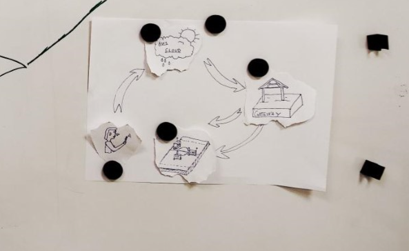
The basic concept of the game (reminiscent of capture the flag)
There are two teams competing. Each is given a digital user interface, which is used to interact with the game and to give feedback to the teams. The game is played out on a court, that is, a rectangular board containing two finishing lines between the center and two opposing edges, see the image below. The goal of the game is to cross the finishing line of the opposing side, and the game is over when the first team reaches the goal.
A gateway keeps track of the availability of the physical robots and reports a list to the Game Administrator, which then assigns robots to the teams. The robots are placed behind the finishing line on the closest edge to the team by the players themselves. The Game Administrator will position the robots in the user interface accordingly.
The game is played out in rounds. During each round, both players configure their actions, commit this configuration and the actions are executed. The configuration of each player is hidden from the opponent.
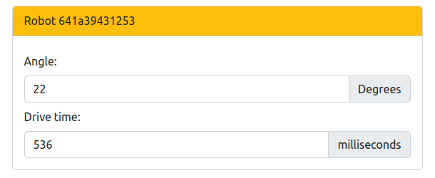
The actions that the players can do are rotating the robots (determined by the angle input) and driving the robots forward for a certain amount of time (determined by drive time input). The robots can be rotated 180 in both directions, and a limit will be set on the drive time. The players may configure the robots repeatedly until they lock in their answers. When both players have locked their configuration, the gateway will forward the configuration to all robots. All robots are configured before execution starts and movement happens simultaneously. Rotation is executed before driving. The gateway will inform the game when the robots have moved and will report back the movements from the user commands.
The Game Administrator updates the positions in the user interface according to the physical positions on the court. If no robot has crossed the finishing line, the next round is initiated, and the players may start the configuration of the next round. If one team has crossed the finishing line, this team is the winner. If both players reach the finishing line with the same number of robots, it is a draw. If they do not have the same number of robots across the finishing line, the winner is the one with the most robots across the line. The Game Administrator determines the winner based on these rules. The game is now over and is reset in order to start a new game.
Technical overview
The figure below shows how the different components in the game communicate with each other.
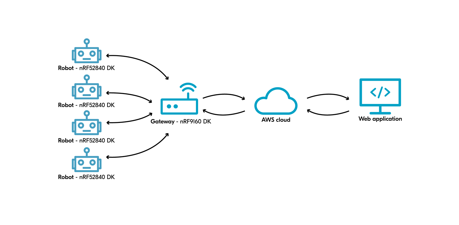
The game starts with the robots, the nRF52840 Development Kits (DK). When they are turned on, they send a message to the gateway, an nRF9160 DK. Once the gateway receives the message, it sends a message to AWS (Amazon Web Services) saying the robots are ready to play. The web application fetches this information and displays it to the user. The user then decides where the robot should go in terms of direction and speed, and this information is sent to the robots through AWS and the gateway. The figure below shows the communication flow.
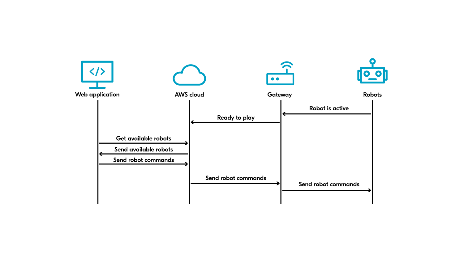
The communication in the system uses different protocols; Bluetooth Mesh, LTE and HTTP. Bluetooth Mesh is the protocol used in the communication between robots and Gateway. The communication between the gateway and AWS is using MQTT over LTE, and the communication between AWS and the Web Application is over HTTP.
The cloud (AWS)
AWS IoT is used for communication between the gateway and the web application. It is a service for connecting IoT devices to other devices and to AWS cloud services. As mentioned, the gateway is an nRF9160 DK connected to an account on AWS. The messages are sent to the gateway using the MQTT protocol which uses a publish/subscribe model. A set of topics are created for each gateway.
 AWS IoT publishes the desired configurations to these topics which the gateways subscribe to. When the gateway receives a new configuration, it decodes it and forwards it to the appropriate robots over Bluetooth Mesh. AWS IoT can then send an “all clear” signal to the gateway, which tells the robots to move as described by the configuration.
For sending commands from the web application to the robots, the user needs to provide an existing Access key ID and Secret Access key to connect the app to a gateway on AWS IoT. The application communicates with the gateway through the device shadow. To connect to the device shadow, we use a client called IoTDataPlaneClient.
It implements a broker for application and things to publish messages over HTTP. All messages communicated through AWS are in JSON format.
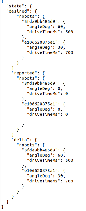
The device shadow in AWS IoT has four different properties: state, desired, reported and delta as shown in the image to the right. The desired property contains the values sent from the user input in the application to the device, the reported property contains the values sent from the device to the application and the delta is the difference between reported and desired values. In the current game state, the robots do not report anything new back, they only send the desired values back again as reported values. This is done to make it easier to add new values later if needed.
The web application
The web application is implemented using React and Typescript. All the game logic is implemented in a game engine that is fully disconnected from cloud communication. For the application to work as intended, you need at least two teams and one Game Administrator. The main pages for the application itself are the Game page and the Admin page.
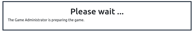
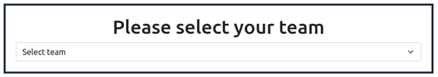
Before the robots are assigned to teams on the Admin Page, a “Please wait” pop-up box is displayed. When the teams are assigned, you will get a pop-up box giving you the possibility to select your team.
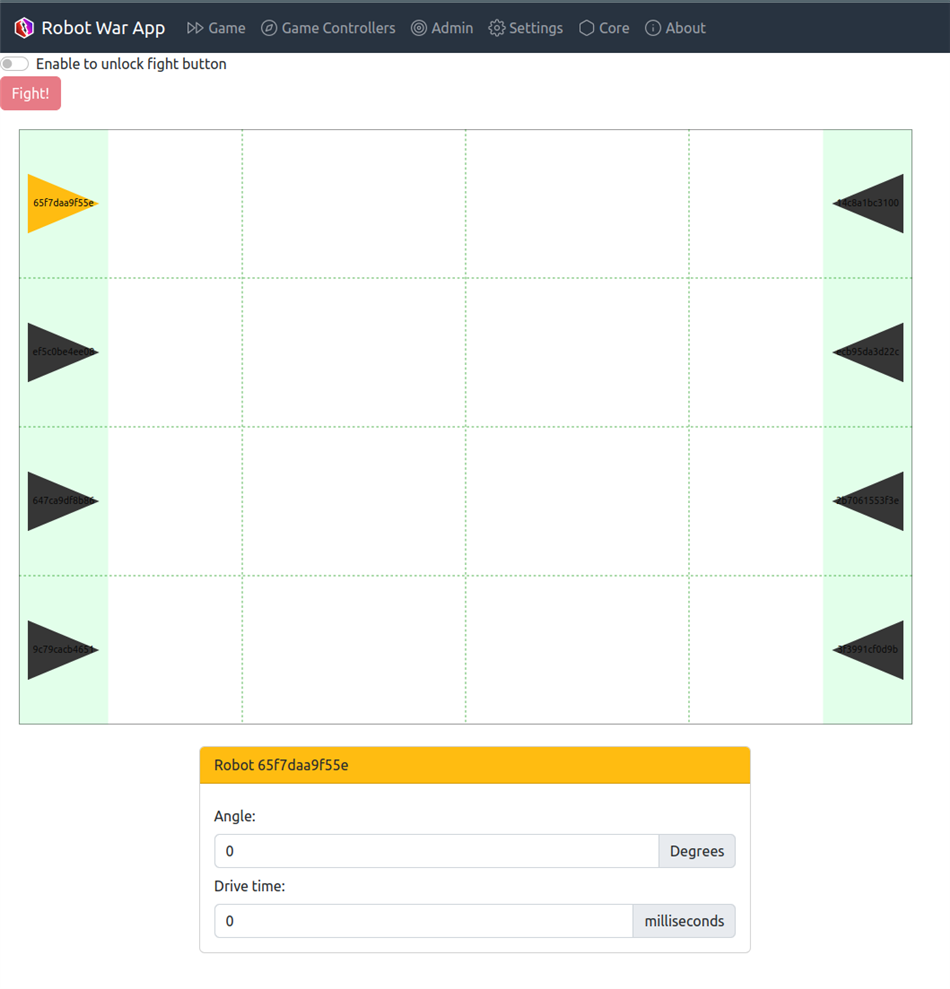
The Game page allows users to assign different angles and drive time to the robots by clicking and dragging the robots on their team. There is also the option to manually add these values in the entry boxes at the bottom of the page, as shown in the figure below (right).
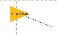
When a team is finished assigning values to their robots, they can select the “Fight”-button indicating that they are ready to fight. When all teams are ready, the Game Administrator will be allowed to move the robots on the admin page to update the positions.
The Admin page is where the robots are assigned to teams, and all teams get a unique color. Assignment of teams is done by typing in the team name. After this is done once, it will show up as an option for the rest of the robots.
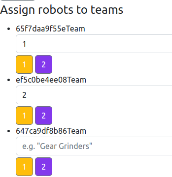
The Admin page also manages the positioning of the robots on the playing field. After each round, when the robots are moved in real life, you can update the positions of the robots through the Admin page by selecting a robot and dropping it down anywhere on the field with a mouse click. There is also a button that gives the Game Administrator the possibility to notify that they are finished moving the robots for this round. When this button is pushed, the positions on the Game page will be updated and the teams will be allowed to assign a new angle and drivetime to the robots.
In the development of the application, we needed to test the application and communication with the cloud without being dependent on reports from the gateway. This was solved by creating a Game Controller page that simulates the behavior of the gateway.
Firmware
The project has three separate but connected firmware. Two of them go on the gateway, the nRF9160 DK, one for the nRF9160 SiP and one for the nRF52840 SoC. The last is for the nRF52840 DK acting as the robots. All the firmware is built on the Application Event Manager system provided in the nRF Connect SDK.
The nRF9160 SiP firmware is responsible for communicating with AWS over LTE. It sets up and manages the AWS connection, subscribes to relevant topics, receives configuration updates, and reports the state of the system back to AWS. It also relays configuration updates and messages for the robots to the gateway's nRF52840 SoC over UART.
The nRF52840 SoC on the gateway is responsible for communicating directly with the robots over Bluetooth Mesh. We originally tried to avoid writing custom firmware for this MCU by using the “Bluetooth: HCI UART” sample in the nRF Connect SDK. Running this sample on the nRF52840 SoC on the gateway would expose the nRF52840’s Bluetooth controller to the nRF9160 SiP over UART. This would have allowed us to run the Bluetooth Mesh software stack on the nRF9160 which in turn would have removed the need to develop and maintain a separate firmware for the gateway nRF52840 SoC. This worked for a while, but after a seemingly random amount of time, the communication between the nRF9160 and nRF52840 would fail, crashing the system. In the end, we had to abandon HCI in favor of a simpler, more stable communication protocol between the MCUs. Instead of sending low-level Bluetooth control messages over UART, we opted to use robot messages as the unit of communication between the gateway nRF9160 and gateway nRF52840. This eased the burden on message transmission as less data needed to be sent, but it meant that we had to create another firmware for the gateway nRF52840 which drastically increased the amount of boilerplate code that had to be written.
The robot firmware receives messages from the mesh network, actuates the motors, and reports some telemetry back to the gateway.
Having three separate firmware that needed to be maintained and coordinated ended up being a major hurdle for the development of the project. Almost any small change anywhere ended up cascading through all the different systems. Looking back, it might have been a good idea to spend some more time trying to make HCI (or some other mechanism for inter-MCU communication) work.
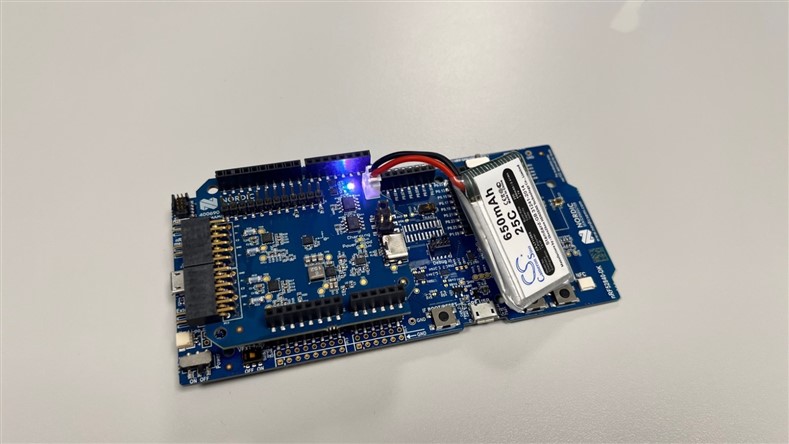
Shield
For the robots to be able to move in the real world, the commands need to be translated into motor rotation. This is done through a custom motor driver shield, which is designed to be compatible with the nRF52840 DK, nRF9160 DK, and nRF5340 DK. The shield powers the motors and DK with a LiPo battery, which can be recharged using a USB-C connector. The header placement follows the standard Arduino Shield pinout, which makes it compatible with many other microcontroller boards as well. However, the shield supplies the DK with power through the VIN 3-5V pin which is not standard. It is therefore most suited for the previously specified nRF DKs. The motors can be individually controlled with a direction signal and a PWM signal. With these inputs, the robot can drive forwards, backwards, and rotate around its axis.
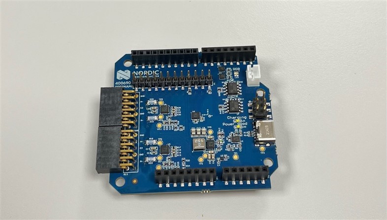
The shield also contains an Inertial Measurement Unit, which measures acceleration and rotation.
By performing processing on the acceleration, rotation, and wheel position data, it is possible to measure and compensate for differences in the driving strength of each motor. This allows the robot to drive in a perfectly straight line, even on slightly rough surfaces.
Closing
The source code to all the components can be found on GitHub, through the following links:
- nRF Robot War Firmware
- nRF Robot War Web Application
- nRF Robot War AWS backend
- nRF Robot War Shield
- nRF Robot War Body
A thought for the future is to implement a method for the robots to report their positions on the playing field back to AWS, so that there is no need for the Game Administrator. It would also be ideal to hide some of the test features implemented on the web application from the regular user and make it only visible to developers.
Do you want more content like this? Feel free to like this blog post and leave a comment below.

