

If you are a human, as opposed to a microcontroller, you might want an easy and intuitive way to read out data from your application. Adding a small OLED display to your project is a simple solution for this. Low-cost OLED displays are easily available, making them perfect for prototyping and DIY projects.
This guide will show how you can to set up the nRF5340 DK with a tiny OLED display based on the SSD1306 display driver IC. We will cover:
- Displaying text on an OLED display
- Setting up a sample using the I2C interface
- Making use of a shield in Zephyr
- Using a driver
- Changing pins in a project
The post is divided into two parts. Part 1 will cover outputting the text Hello World! to the display and part 2 will look at changing the pins in the project and modifying the content displayed.
Zephyr has numerous available display samples, and this guide will use the LittlevGL Basic Sample, or lvgl in short. To simplify the setup, we will make use of the shield functionality in Zephyr, specifically the SSD1306 128x64(/32) pixels generic shield (the hardware used is still the 4-pin I2C module).
Purchasing a display
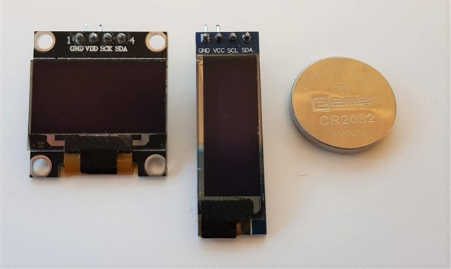
These small display modules come in two sizes (resolution 128x32 or 128x64), both of which are covered in this guide. The available colors are usually either white on black, blue on black or blue and yellow on black. The modules can be bought from various sources, usually costing between 3-5 USD each, depending on the quantity. Search for something like "ssd1306 128x32 i2c oled display", for example on Amazon or Ebay. The modules are often poorly documented. Worth knowing is that they usually handle 3-5 Vin. The display driver IC is likely Solomon Systech SSD1306 (some features are listed, datasheet available on request). The modules come with or without a mounted pin list (4-pins). There is also an SPI shield with a corresponding Zephyr shield though this is not covered in this guide.
The image below shows two OLED display modules in resolution 128x64 (left) and 128x32 (right) with a CR2032 for scale.
Software prerequisites
- nRF Connect SDK set up and ready to use on your computer. The code in the post has been tested using nRF Connect SDK v2.1.0. Older versions of the SDK will work if the device tree overlay is adapted.
- The steps are shown using nRF Connect for VS Code. Command line users will be able to follow.
- The lvgl sample is already included in the SDK. The sample is based on the Little vGL, https://lvgl.io/
- The code for both Part 1 and 2 is available on GitHub: https://github.com/hx91/oled-ssd1306-lvgl.
Hardware components needed
- An nRF5340 DK (it should be straightforward to use other DKs, such as the nRF9160 DK) by making minor modifications to the pin numbering in the code).
- An I2C OLED display module, based on the SSD1306 driver IC (both the 128x32 and 128x64 versions are covered in this text).
- 2 or 4 short jumper wires (female-male). No soldering iron is needed if you buy modules with a mounted pin list.
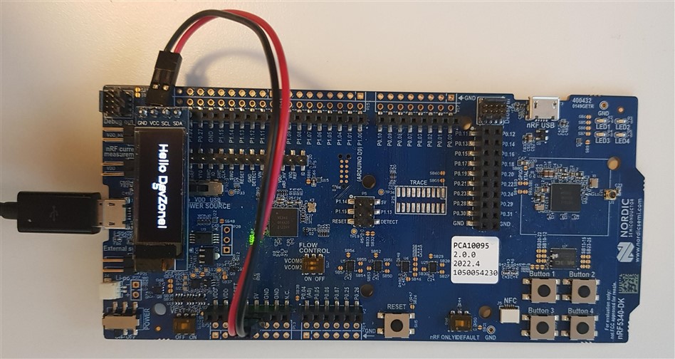
Hardware setup
Wire the display to the DK according to the table below, depending on which DK you are using. The easiest way is using four female-male jumper wires from the module to the DK.
| nRF5340 DK pin | nRF9160 DK pin | Arduino pin header name | Display pin |
| P1.02 | P0.30 | D18/SDA | SDA |
| P1.03 | P0.31 | D19/SCL | SCL |
| GND | GND | GND | GND |
| VDD or 5V | VDD or 5V | 3.3V or 5V | VCC |
Table 1: Wiring the display to the nRF5340 DK or nRF9160 DK
Part 1 - Outputting Hello World! to the OLED display
The following steps show how to adapt the lvgl sample before flashing it to the DK and observing the text output on the display.
- Create a new application from the welcome screen in the nRF Connect for extension for VS Code.
- Select the nRF Connect SDK version (v2.1.0 in this guide), and where to keep the project files (for example
C:\projects\oled). Choose 'Freestanding'.
In the Application template field type 'lvgl' and select the sample inzephyr/samples/subsys/display/lvgl(or click 'Browse…' to have a glance at the lvgl sample documentation.
Click "Create Application". - Create a Build configuration and select the correct board,
nrf5340dk_nrf5340_cpuapp(or, if using the nRF9160 DK,nrf9160dk_nrf9160_ns).
Uncheck "Build after generating configuration" as we need to create an overlay before building. - Include the shield in the project by opening
CMakeLists.txtand then adding the lineset(SHIELD ssd1306_128x32)just below the line that sayscmake_minimum_required(VERSION 3.20.0)(or addset(SHIELD ssd1306_128x64)if using the 128x64 version).
As an alternative one may add-DSHIELD:STRING="ssd1306_128x32"as an Extra CMake argument. If using the latter method, double-check that the Extra CMake argument has not disappeared after clicking Generate Configuration. - Create an overlay file,
nrf5340dk_nrf5340_cpuapp.overlay' in your project folder. Add the following to the overlay:arduino_i2c: &i2c1 { compatible = "nordic,nrf-twim"; status = "okay"; clock-frequency = <I2C_BITRATE_FAST>; zephyr,concat-buf-size = <4096>; };
Edit: For nRF52832: Usecompatible = "nordic,nrf-twi";instead ofcompatible = "nordic,nrf-twim";also remove the linezephyr,concat-buf-size = <4096>; - Wire the display to the DK according to Table 1. Edit: If using nRF9160 DK, set the VDD_IO pin to '3V'.
- Now build (using the Pristine build button since we changed the overlay) and flash the board by clicking "Erase and flash" and observe that the display goes white with dark letters "
Hello World!" on the OLED display!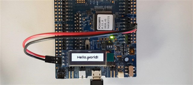
Part 2 - Modifying the contents displayed and changing the pins
Let's look at further customizing the sample, by changing pins, configuring the driver, and choosing what to display.
The ssd1306 shield in the SDK contains overlay files and Kconfigs that become active when the shield is in use. The use of shields largely simplifies the process of getting started. However, when things are not working, it is a good idea to look in the shield and driver folders:
- ssd1306 shield folder:
zephyr\boards\shields\ssd1306. - ssd1306 driver:
zephyr\drivers\display\, includingssd1306.candssd1306_regs.h.
- Copy the overlay from the shield into your project's overlay file: Go to the ssd1306 shield folder (
zephyr\boards\shields\ssd1306)and open the file that corresponds to your display. In this case, openssd1306_128x32.overlayfor the I2C version of the 128x32 pixel module based on the SSD1306 IC (orssd1306_128x64.overlayfor the 128x64 version). This overlay file is already being used by the project. However, since we would like to make a few changes, we copy the contents into our overlay file (nrf5340dk_nrf5340_cpuapp.overlayornrf9160dk_nrf9160_ns.overlay). The changes we make in our project's overlay file will overwrite the shield's overlay (which in turn overwrites the board files for the DK). See the solomon,ssd1306fb (on i2c bus) driver documentation for available driver options. - Modify the driver settings. Within
ssd1306: ssd1306@3c {};is where you specify the driver settings and define the properties of the display.width = <128>;is an obvious example, where you let the driver know that your display is, in fact, 128 pixels wide. Check out the SSD1306 driver documentation to see more properties that can help you configure and fine-tune the display driver IC. - Copy Pin Control configuration from the DK's board files into your own project's overlay: Open the DK's
.dtsifile from the board folder:zephyr\boards\arm\nrf5340dk_nrf5340\nrf5340_cpuapp_common-pinctrl.dtsi. For nRF5340 DK, search for 'i2c1' in this file. We will now see thati2c1is set up withP1.2(port 1, pin 2) asSDAandP1.03(port 1, pin 3) asSCL. We now copy this section and wrap it withinpinctrl. The complete overlay looks as follows:&pinctrl { i2c1_default: i2c1_default { group1 { psels = <NRF_PSEL(TWIM_SDA, 1, 2)>, // GPIO P1.2 <NRF_PSEL(TWIM_SCL, 1, 3)>; // GPIO P1.3 }; }; i2c1_sleep: i2c1_sleep { group1 { psels = <NRF_PSEL(TWIM_SDA, 1, 2)>, // GPIO P1.2 <NRF_PSEL(TWIM_SCL, 1, 3)>; // GPIO P1.3 low-power-enable; }; }; }; arduino_i2c: &i2c1 { compatible = "nordic,nrf-twim"; status = "okay"; clock-frequency = <I2C_BITRATE_FAST>; zephyr,concat-buf-size = <4096>; ssd1306: ssd1306@3c { compatible = "solomon,ssd1306fb"; reg = <0x3c>; //0x3c is the i2c address of the SSD1306 aIC. width = <128>; height = <32>; // Change to '64' when using the 128x64 pixel version. segment-offset = <0>; page-offset = <0>; display-offset = <0>; multiplex-ratio = <31>; //change to '63' when using the 128x64 pixel version segment-remap; com-invdir; com-sequential; prechargep = <0x22>; }; };
If we want to change which pin on the DK should be used asSDAandSCL, this is the code that needs to be changed. For example, when using nRF9160 DK, you could change topsels = <NRF_PSEL(TWIM_SDA, 0, 30)>, // P0.30 . psels = <NRF_PSEL(TWIM_SCL, 0, 31)>, // P0.31
Remember to change both for default and sleep. - Add the KConfig below: Open
prj.conf, located in the project folder, and add the following lineCONFIG_SSD1306_REVERSE_MODE=y
This will invert the display and result in a bright font on a dark background. - To change the contents of the display, open
main.clocated insrcin the project folder. Search for 'Hello World'and replace with the text of your choice. Here you also see how the LittlevGL library is used. - Connect to the terminal to see extra information and errors from the application. This is useful when working with displays that remain dark or display something unexpected.
- Do a Pristine build and flash the board to observe the changes. Later, when you are not updating the overlay and only updating the application, you can do the normal build, which is faster.
A few notes
- In some circumstances, even if errors or mistakes are made, one may still see the old image on the display from a previous build. If you observe the incrementation of the counter on the display you can visually verify that the application is running and that the display is being updated.
- The LittlevGL library can be found here: lvgl.io
- Another fun sample to try is the Character Framebuffer Shell Module Sample where you type text into the terminal and see it directly on the OLED display.
- The code used in this project can be found here: https://github.com/hx91/oled-ssd1306-lvgl.


