

**Project and hex files for testing this is attached in the end of this blog.
Introduction
There has been a lot of discussion/testing/confusion about testing the long range feature of Bluetooth Low Energy (BLE) with Nordic Semiconductors latest chip nRF52840 Rev C. This blog post demonstrates that the long range feature works the way it is supposed to. You can test it yourself with the attached project/binaries
The intention of this blog post is to:
- Compare 1M PHY with Coded PHY in term of range you can achieve (outdoors) in connected and non-connected states.
- Give you a complete, clear, and descriptive setup, so that you can reproduce the results mentioned in this post easily.
- Make a few things clear about the difference in testing long range outdoors and indoors
There are two ways how you can increase range in your BLE product. Before Bluetooth 5 (BT5), there was only one way to do that, namely by increasing the radio transmit power. But doing so, will significantly increase the average current of your product. And the other is by using the long range feature newly introduced by BT5.
You should also know a bit about path loss, which is explained a bit clearer in this external post. Note that just considering the air path loss (thus not considering the signal loss due to absorption by materials in the path)the post gives the following information:
"Path Loss
Path loss is the reduction in power density that occurs as a radio wave propagates over a distance. The primary factor in path loss is the decrease in signal strength over distance of the radio waves themselves. Radio waves follow an inverse square law for power density: the power density is proportional to the inverse square of the distance. Every time you double the distance, you receive only one-fourth the power. This means that every 6-dBm increase in output power doubles the possible distance that is achievable."
But in the real world, the path loss is a little bit more than the ideal air path loss. This is due to the precipitation, humidity, reflected signals, and so on, which deteriorates the signal more in the path.
Understanding the obtained long range results?
This blog post aims at making it simple for you to analyze the results you get with long range. The places where you test long range will surely have different signal propagation characteristics and different path losses than the places where I tested this. To make it simple and to keep these random variables that will affect your range out of the equation, we will do the range test with both 1M PHY and Coded PHY (long range) and compare the results. This way we can minimize the effect of all the random variables on the radio signal and concentrate solely on the improvement that the long range feature gives over 1M PHY.
Why are we not doing this test indoors?
This is because your indoors architecture is not symmetric. The results I get in my office/home building will be very different that the results you get where you do this test. The surrounding materials around you indoors, does not cause linear path loss like outdoors (it might not be a linear path loss even outdoors if the landscape you choose is not a plain open ground). This is due to the difference in the absorption/reflection/diffraction properties of materials around you. This is also the reason why I am doing this test outdoor, to keep this as simple as possible.
Test Setup and Equipment
3 x PCA10056v0.12.0 (at least nRF52840 with Rev C chip)
Power supply (coin cell battery or USB power bank)
Let me stress that this experiment is not about determining the power consumption of long range, but about testing the comparable range between 1M and coded PHYs. Since the adv/scan/connection parameters are set to a very low value, this experiment is not power-friendly. It will therefore drain your coin cell battery faster than you expect. This is because we are trying to keep the radio active most of the time, and were also using LEDs as a visual tool. I recommend you use a USB power bank, to get a steady power supply throughout your test. Of course this is not the requirement of this setup, so you can also use a coin cell battery, if you do not have any USB power bank handy.
Attached is a simplified ATT_MTU project at the end of this blog, that you should unzip into the SDK15\examples\ble_central_and_peripheral\experimental folder. I have tested this with Keil, so I deleted other versions of the compiler projects to remove confusion and irregularities (keeping it simple)
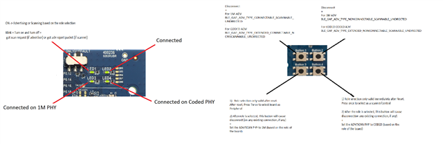
The button and LED assignment is as shown in the picture:
Holding your test kits in the correct position/direction
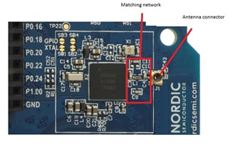
The picture below shows the front side of the DK, where you can see the Nordic chip (nRF52840), the matching network (marked with a red box), and the connector for the external antenna. We are not using an external antenna, and just using the PCB antenna that is printed on board. So with this specific PDK, the radio pattern radiates strongest on the front side. It radiates on the backside of the PDK as well, but you will observe a radio signal strength loss of about 3-4 dBm on the backside. This is due to many reasons (material of PDK, underlying printed metal circuit, etc). Therefore, it is best that when you are testing with PDKs, you set them facing each other as shown below. They do not need to be aligned to the same altitude. Facing them each other with any individual altitude should be ok.
 .
.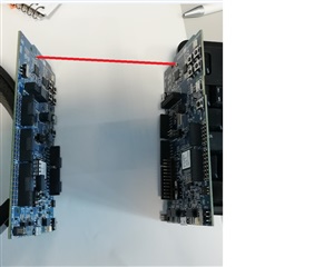
You might ask yourself if this is really required? Well, It is not absolutely necessary that the PDKs face each other for this test, but you MUST be consistent in positioning your PDKs in the same direction for both the 1M range test and the Coded PHY range test. This way the signal loss due to the material of the PDK for both tests will remain constant and hence the range comparison results would look reasonable.
Now, lets program the boards and start testing!
We need 3 PCA10056 DK with atleast a RevC Nordic chip. I will from now refer to the kits as Alpha, Beta, and Omega to avoid confusion.
Testing non connected states (0 dBm Tx power):
- Do a chip erase to start fresh with all DKs. You can use comand line ("nrfjprog -e -f nrf52") or use nrfConnect app.
- Flash the softdevice s140_nrf52_6.0.0_softdevice.hex file into all the kits. (by using nrfjprog in command line or using nrfConnect app)
- Now unzip the file ble_app_att_mtu_throughput_test.zip into your PATH_TO_SDK15\examples\ble_central_and_peripheral\experimental and open the project PATH_TO_SDK15\examples\ble_central_and_peripheral\experimental\ble_app_att_mtu_throughput_test\pca10056\s140\arm5_no_packs\ble_app_att_mtu_throughput_pca10056_s140.uvprojx.
- Testing from precompiled hex. Flash non_connected_0dBm.hex file to Alpha and Beta from the attached zip folder and go directly to step 9.
- Not testing the precompiled hex files? then continue here. in main.c, change the define CONNECT_TO_ADV_REPORT to 0. With this configuration, the scanner does not send any connect requests to the adv report with matching device name. The scanner just blinks the LED1 once when it for the adv report from matching device name and continues scanning. The peer advertiser will blink LED1 for any scan request it gets (not filtered by peer address). So I would recommend you to connect the scanner to the PC to get logs instead of advertiser. Since scanner filters adv reports and only logs events from advertiser with name DEVICE_NAME (sdk_config.h)
- Compile the program (ignore the warnings, I would like to clean up the app, but I want you to use exactly the same setup that I used, not changing even one line).
- Flash the program to Alpha and Beta.
- Change CONNECT_TO_ADV_REPORT 1, compile the program, and flash the program to Omega. Ignore step 9 since we are not testing precompiled hex files.
- Flash connected_0dBm.hex file to Omega.
- Reset both boards Alpha and Beta. Press Button 3 twice on Alpha, which will make it a connectable-scannable advertiser with interval 50ms on 1M PHY.
- Press Button 4 on Beta, which will make it a scanner with a 100 ms scan window and the same scan interval. This way, it will be scanning all the time (which is why these tests are not power-friendly). But we are not testing power consumption here, we are doing a range comparison of two PHYs! At this point, you will see that LED1 on two boards are blinking fast. Alpha will blink LED1 for any scan request packet it gets (not matching a device name here, so please test this in a Bluetooth-free zone outdoors). Beta will blink LED1 once only if it gets an adv packet from the peer with DEVICE_NAME (sdk_config.h) as device name set in the adv packet.
- Now hold these two devices so that they face each other (as shown in the image earlier) and increase the distance between the two devices. In my test we were two people, holding one PDK each and walking away till we did not see any LED1 blink. You can connect these devices to a PC with a COM port listener and check the logs that shows the RSSI value. In my test I connected Beta to the laptop to see if I am getting any packets from Alpha. This was more effective as Beta is filtering adv packets before it toggles the LED.
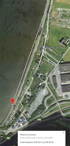
- Increase the distance between the two devices (yet maintaining line of sight) until Beta does not get any packets from Alpha (LED1 does not blink on either of the devices anymore). You should see that the last received packet has an RSSI of around -92 or 93 dBm. Determine the distance between these two devices, for example using a GPS location marker on the phone. Lets say the distance is X1M meters.
- Now switch PHY from 1M to Coded by pressing Button 4 on both boards.By default, Alpha will now transmit BLE_GAP_ADV_TYPE_EXTENDED_CONNECTABLE_NONSCANNABLE_UNDIRECTED packets and you will see that Beta blinks LED1 when it gets adv packet only from Alpha. On Alpha LED1 will not blink as it transmits non scannable packets and does not know about the presence of Beta. (Note: You can make Alpha transmit scannable packets by pressing Button2 on it. For reference, see the image with the button and led mapping shown earlier.)
- Repeat Step 8 to determine the maximum distance based on the blinking LED1 on Beta. Lets say you got a distance of Y1M meters.
- So the improved range in percentage with Coded PHY compared to 1M PHY can be formulated as ((Y1M - X1M) * 100)/X1M.
The distance I got for 1M PHY 0 dBm TX was 654.92 meters.
The distance I got for Coded PHY 0 dBm TX was 1300 meters.
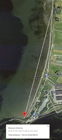
So the range increase was ((1300 - 654.92) * 100 ) / 654.92 = 98.49% increase in range with Coded PHY compared to 1M in non connected state at 0 dBm.
Testing connected states (0 dBm Tx power)
- Make sure that you have three boards Alpha, Beta and Omega flashed mentioned in steps for flashing the DKs in non-connected states test above. If you have already performed non connected states test, then you have DKs ready and no need to reprogram them again.
- Reset both boards Alpha and Omega. Press Button 3 twice on Alpha, which will make it a connectable-scannable advertiser with interval 50 ms on 1M PHY.
- Press Button 4 on Omega, which will make it a scanner with a 100 ms scan window and the same scan interval. This way, it will be scanning all the time. As soon as Omega sees an adv packet from Alpha, it will immediately send a connect request and connect to Alpha(Alpha will stop advertising and Omega will stop scanning after a connection is established)
- Now LED2 and LED3 on both boards will light up, indicating that the boards are connected on 1M PHY.
- Increase the distance between the two devices (yet maintaining line of sight) until both devices disconnect and are unable to reconnect even after few seconds. Note the location where you cannot make the two devices connect back after disconnection. Calculate the distance between these two devices using any method you feel comfortable. I used GPS location marker on phone. Lets say you have got X2M meters
- Now switch PHY from 1M to Coded by pressing Button 4 on both boards.By default, You will see that LED2 and LED4 light up on both boards showing that the connection has been established on Coded PHY.
- Repeat step 4 and get the max distance until the devices wont connect again (there might be few disconnection based on the terrain, but I normally note the point where I cannot make the two devices reconnect again few seconds after disconnect. This is to see the range of when the devices can detect connect request). Lets say you got Y2M meters.
- So the improved range in percentage with Coded PHY compared to 1M can be formulated as ((Y2M - X2M) * 100)/X2M.
The distance I got for 1M PHY 0 dBm TX in a connection was 681.90 meters.
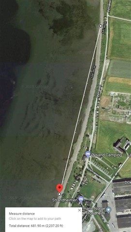
The distance I got for Coded PHY 0 dBm TX in a connection was 1300 meters.
So the range increase was ((1300 - 681.9) * 100 ) / 681.9 = 90.64% increase in range with Coded PHY compared to 1M in connected state at 0 dBm.
why is there a small difference in non connected and connected state? Technically there should not be, but there are many variables that can affect this range. If this difference is consistent in our future tests, then we will try to analyze it in a different blog post.
Testing connected states (8 dBm Tx power)
You can perform the whole test again changing the radio TX power to 8 dBm for adv/connections to clearly see that the range now significantly increases. In the project you can do it by changing RADIO_TX_POWER to 8 and restarting the test from the section "Testing non connected states".
Conclusion
There are several conclusions that can be drawn from this test:
- With 1M PHY, the scanner logs show that we can get adv packets with a signal strength of around -93 dBm. With Coded PHY, the scanner can still detect adv packets of signal strength around -101 dBm. This is clearly an improvement in radio sensitivity and the proof of this feature working.
- Since we have established that radio sensitivity has improved a lot in Coded PHY, it is a matter of correlating this improved radio sensitivity to the use cases. If you see 6 dBm improved sensitivity using Coded PHY, you cannot expect double the range improvement at any place. The range improvement will also depend on the radio propagation characteristics (which are outside the control of this BT5 feature). For example, when you are testing this indoors, the absorption/reflection/diffraction of the radio signal by the different types of materials around will significantly deteriorate the signal along its path. But one thing is still pretty clear about using the long range feature, You should definitely get increased range as compared to 1M PHY (how much increase will depend on surroundings and is impossible to generalize). If you get double the range using Coded PHY outdoors, does not mean that you will get the same improvement indoors.
- We tested with nRF52840 Rev C(PCA10056 v0.12.0 PDK), SDK15, and S140 v6.0.0 and conclude that long range works. If you achieve similar results with the given PDK, but cannot achieve the same with your custom hardware, then we know that the issue is somewhere else and not with latest Nordic solution. (You should then dig into board design/schematics/layouts/plastic material surrounding the radio etc.)
Please ask questions if you have any. We will try to answer to as many as we can.
Please post your achieved range in different configuration and the GPS location so that we know more about your achievements.
Happy Testing
Project and binary attachment below

Top Comments
-
$core_v2_ui.GetResizedImageHtml($comment.User.AvatarUrl, 44, 44, "%{border='0px', alt=$comment.User.DisplayName, ResizeMethod='ZoomAndCrop'}")
$core_v2_ui.UserPresence($comment.User.Id)
$comment.User.DisplayName
-
Cancel
-
Vote Up
$currentVotes.ToString("+0;-0;0")
Vote Down
-
$core_v2_ui.Like($comment.CommentId, $comment.CommentContentTypeId, "%{ Format = $likeFormat, IncludeTip = 'true' }")
-
Sign in to reply
-
More
-
Cancel
Children