NUS with nRF Connect SDK: Wireless UART with the nRF Connect SDK
This year Nordic is transitioning from the nRF5 SDK to the nRF Connect SDK (SDK) as part of an effort to expand the power and breadth of our software offerings. With the integration of the Zephyr RTOS and a new paradigm for Nordic BLE moving from the Soft Device model to a more open source approach, the nRF Connect SDK will enable a new generation of applications for the nRF52 family, the nRF5340 and beyond. As a Nordic Field Application Engineer, I often work with engineers as they learn about Nordic components and software. Often, a great starting place for individuals looking to learn about the fundamentals of BLE and how to create their own custom BLE applications has been with the Nordic UART Service (NUS). The Nordic UART Service is a custom service created by Nordic to act as a simple wireless UART. In a typical scenario, one nRF device, acting in the central role, automatically finds and connects to another Nordic device acting as a NUS peripheral. Alternatively, one of the devices could be a mobile device. The two devices form a wireless data pipe. Text entered on one end will be sent to the other end. For some engineers, this basic application can be enough to prototype a simple system to stream data and commands wirelessly from one location to another. This post will walk you through the steps to get started with the Nordic UART Service with the nRF Connect SDK. We’ll go over setting up the environment, go over the NUS projects in the nRF Connect SDK taking a look at configuration and the main programs, and then build, program, and test the Nordic UART Service.
Installing the nRF Connect SDK
If you’re new to NCS, you should start with the nRF Connect SDK Tutorial Series. You should also download nRF Connect for Desktop and install NCS with the Toolchain Manager. The NCS tutorial series is an excellent introduction that teaches you how to set up your development environment, about the fundamental components and features of NCS, and how to work with NCS to create a custom application. In this tutorial, we’ll look at each of the parts of the NUS project to see what’s going on under the hood and then build, flash, and run the Nordic UART Service.
Once you get the nRF Connect SDK installed, locate the NCS folder on your hard drive. If you used the Toolchain Manager, you’ll have a folder on your computer where the nRF Connect SDK has been downloaded. On my computer, it’s C:\NCS. Within that folder, I have subfolders for different versions of NCS. Under each folder are all the components of NCS, some of which are contributed by Nordic and others which are forked from the Zephyr Project. All of the samples developed and maintained by Nordic can be found in <..>\NCS\v1.x.0\nrf\samples. For this tutorial, we’re looking at the Bluetooth examples which are found in the Bluetooth subfolder. Specifically, the two projects we’ll use are the “central_uart” example and the “peripheral_uart” example. The names indicate that in the “central_uart” example, the device will act as a BLE Central Device and in the “peripheral_uart” example, the device will act as a BLE “peripheral”. Let’s look at each one. We’ll see that they are mostly the same with a few key differences, a fact which hints at the utility and flexibility of the nRF Connect SDK.
Note for the nRF5340
In this tutorial, I’ll be using a pair of 52840-DKs as my example hardware. The process is mostly the same for the nRF5340 but there are some extra required steps. If you are using the nRF5340 for this tutorial, you’ll need to flash the network processor with the hci_rpmsg project in the <..>\NCS\v1.x.0\zephyr\samples\bluetooth folder. This programs the network processor with the lower level portions of the BLE stack. You’ll also need to select the nRF5340DK board and the application processor as the target at the appropriate step too. Otherwise, everything is the same. Again, that’s pretty neat and a testament to the new SDK. For more information about this, consult the nRF Connect SDK documentation.
Nordic UART Service: The Peripheral Device
Let’s start with the peripheral side of the Nordic UART Service. If you’ve only got one Nordic Development Kit, then you’ll only need to build and flash the peripheral project and you can use a mobile phone as the central device. You can follow the peripheral UART instructions below and then jump down to testing.
Project Configuration
Before running the project, let’s look at how the peripheral_uart project is configured. NCS, as a fork of Zephyr, introduces a new paradigm for project configuration. Borrowing from the open source community, NCS projects are configured using project configuration files. The primary configuration file is called prj.conf, which can be found at the top level of each of the example folders. The prj.conf file can be edited directly to change the project configuration, from the command line via menuconfig, or from within Segger Embedded Studio. Just remember that changes made in Segger Embedded Studio or with menuconfig need to be copied into the prj.conf file in order to be permanent and affect every build in the project folder. Also, if you edit the prj.conf file ouside of SES, you'll need to click Project->Reload to apply the changes to your open project. At the same time, the flexibility of having different builds with different configurations will allow you to try different configurations with the same firmware easily. Let’s look at what’s in the prj.conf file in the Peripheral UART example.
CONFIG_NCS_SAMPLES_DEFAULTS=y

CONFIG_UART_INTERRUPT_DRIVEN=y
CONFIG_UART_0_NRF_FLOW_CONTROL=y
CONFIG_SERIAL=y
CONFIG_GPIO=y

# Make sure printk is not printing to the UART console
CONFIG_CONSOLE=y
CONFIG_UART_CONSOLE=y

CONFIG_HEAP_MEM_POOL_SIZE=2048

CONFIG_BT=y
CONFIG_BT_PERIPHERAL=y
CONFIG_BT_DEVICE_NAME="Nordic_UART_Service"
CONFIG_BT_DEVICE_APPEARANCE=833
CONFIG_BT_MAX_CONN=1
CONFIG_BT_MAX_PAIRED=1

# Enable the NUS service
CONFIG_BT_GATT_NUS=y

# Enable bonding
CONFIG_BT_SETTINGS=y
CONFIG_FLASH=y
CONFIG_FLASH_PAGE_LAYOUT=y
CONFIG_FLASH_MAP=y
CONFIG_NVS=y
CONFIG_SETTINGS=y

# Enable DK LED and Buttons library
CONFIG_DK_LIBRARY=y

# This example requires more workqueue stack
CONFIG_SYSTEM_WORKQUEUE_STACK_SIZE=2048
It’s fairly self-explanatory. Every NCS feature is activated by using the appropriate “CONFIG” setting followed by ‘=y’. These statements inform the Zephyr build system which files to include in building your project. We can see that this prj.conf file enables the UART and GPIO, enables BLE as a peripheral and sets the device name, that the Nordic UART Service is included, and that the features necessary to store bonding information are enabled. Later if we look at the device that’s advertising, we’ll see the device name as it’s written here.
Opening the Project
At the time of writing this tutorial, the best way to open Segger Embedded Studio (SES) for use with the nRF Connect SDK, is through the Toolchain Manager, which is part of the nRF Connect for Desktop suite of apps. Simply open the Toolchain Manager, and click the button labeled “Open IDE”. Once in SES, to open the Peripheral UART project, click File->Open nRF Connect SDK Project… In the pop-up, fill in the CMakeLists.txt box by navigating to your installation of NCS and drilling down to the “peripheral_uart” example. Your exact location will be different from mine and the version of NCS that you are using may have advanced. Also, fill in the board directory by finding the Nordic Development Kit you are using by looking in the <..>/NCS/v1.x.0/zephyr/boards directory. I’m using the 52840 Development Kit in the image below. You may be using any of the other Nordic Development kits. Just make sure you choose the right one. If you are working with the nRF5340, select the cpuappns as the board name.
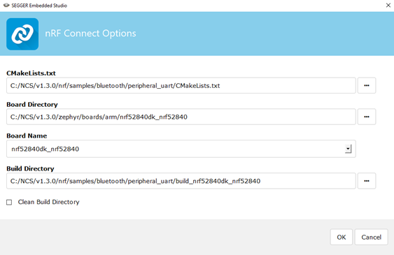
If opening the project fails, it’s a sign that something went wrong in the installation. You should go back and make sure to follow the steps exactly.
Under the Hood: main.c
Now that we’ve seen the project configuration and opened the project, let’s get into main.c to see the inner workings. To get to main.c, click the expand arrow next to “Project ‘app/libapp.a” and dig down until you see main.c. All the other files, modules and such below this in the project were incorporated based on the prj.conf file.

Now, this project and NCS in general, as we’ve said are based on the Zephyr RTOS. So, within main we see many uses of Zephyr RTOS features: threads, data types, semaphores, FIFOs, and lots of BLE goodness. It’s a great example of the power that comes with Nordic’s transition to this new SDK.
I find that it’s helpful to keep a bookmark on the Zephyr API reference to look up various features and learn how to use them. For this tutorial, I used NCS v1.3.0 which is a fork of Zephyr 2.3.0. The main page for this version of Zephyr can be found here: https://docs.zephyrproject.org/2.3.0/. As we go, it will be useful for you to study these Zephyr features. Here's the entire main.c if you don't have the project open at the moment.
/*
 * Copyright (c) 2018 Nordic Semiconductor ASA
 *
 * SPDX-License-Identifier: LicenseRef-BSD-5-Clause-Nordic
 */

/** @file
 *  @brief Nordic UART Bridge Service (NUS) sample
 */

#include <zephyr/types.h>
#include <zephyr.h>
#include <drivers/uart.h>

#include <device.h>
#include <soc.h>

#include <bluetooth/bluetooth.h>
#include <bluetooth/uuid.h>
#include <bluetooth/gatt.h>
#include <bluetooth/hci.h>

#include <bluetooth/services/nus.h>

#include <dk_buttons_and_leds.h>

#include <settings/settings.h>

#include <stdio.h>

#define STACKSIZE               CONFIG_BT_GATT_NUS_THREAD_STACK_SIZE
#define PRIORITY                7

#define DEVICE_NAME             CONFIG_BT_DEVICE_NAME
#define DEVICE_NAME_LEN	        (sizeof(DEVICE_NAME) - 1)

#define RUN_STATUS_LED          DK_LED1
#define RUN_LED_BLINK_INTERVAL  1000

#define CON_STATUS_LED          DK_LED2

#define KEY_PASSKEY_ACCEPT DK_BTN1_MSK
#define KEY_PASSKEY_REJECT DK_BTN2_MSK

#define UART_BUF_SIZE           CONFIG_BT_GATT_NUS_UART_BUFFER_SIZE

static K_SEM_DEFINE(ble_init_ok, 0, 2);

static struct bt_conn *current_conn;
static struct bt_conn *auth_conn;

static struct device *uart;
static bool rx_disabled;

struct uart_data_t {
	void  *fifo_reserved;
	u8_t    data[UART_BUF_SIZE];
	u16_t   len;
};

static K_FIFO_DEFINE(fifo_uart_tx_data);
static K_FIFO_DEFINE(fifo_uart_rx_data);

static const struct bt_data ad[] = {
	BT_DATA_BYTES(BT_DATA_FLAGS, (BT_LE_AD_GENERAL | BT_LE_AD_NO_BREDR)),
	BT_DATA(BT_DATA_NAME_COMPLETE, DEVICE_NAME, DEVICE_NAME_LEN),
};

static const struct bt_data sd[] = {
	BT_DATA_BYTES(BT_DATA_UUID128_ALL, NUS_UUID_SERVICE),
};

static void uart_cb(struct device *uart)
{
	static struct uart_data_t *rx;

	uart_irq_update(uart);

	if (uart_irq_rx_ready(uart)) {
		int data_length;

		if (!rx) {
			rx = k_malloc(sizeof(*rx));
			if (rx) {
				rx->len = 0;
			} else {
				/* Disable UART interface, it will be
				 * enabled again after releasing the buffer.
				 */
				uart_irq_rx_disable(uart);
				rx_disabled = true;

				printk("Not able to allocate UART receive buffer\n");
				return;
			}
		}

		data_length = uart_fifo_read(uart, &rx->data[rx->len],
					     UART_BUF_SIZE-rx->len);
		rx->len += data_length;

		if (rx->len > 0) {
			/* Send buffer to bluetooth unit if either buffer size
			 * is reached or the char \n or \r is received, which
			 * ever comes first
			 */
			if ((rx->len == UART_BUF_SIZE) ||
			   (rx->data[rx->len - 1] == '\n') ||
			   (rx->data[rx->len - 1] == '\r')) {
				k_fifo_put(&fifo_uart_rx_data, rx);
				rx = NULL;
			}
		}
	}

	if (uart_irq_tx_ready(uart)) {
		struct uart_data_t *buf =
			k_fifo_get(&fifo_uart_tx_data, K_NO_WAIT);
		u16_t written = 0;

		/* Nothing in the FIFO, nothing to send */
		if (!buf) {
			uart_irq_tx_disable(uart);
			return;
		}

		while (buf->len > written) {
			written += uart_fifo_fill(uart,
						  &buf->data[written],
						  buf->len - written);
		}

		while (!uart_irq_tx_complete(uart)) {
			/* Wait for the last byte to get
			 * shifted out of the module
			 */
		}

		if (k_fifo_is_empty(&fifo_uart_tx_data)) {
			uart_irq_tx_disable(uart);
		}

		k_free(buf);
	}
}

static int init_uart(void)
{
	uart = device_get_binding("UART_0");
	if (!uart) {
		return -ENXIO;
	}

	uart_irq_callback_set(uart, uart_cb);
	uart_irq_rx_enable(uart);

	return 0;
}

static void connected(struct bt_conn *conn, u8_t err)
{
	char addr[BT_ADDR_LE_STR_LEN];

	if (err) {
		printk("Connection failed (err %u)\n", err);
		return;
	}

	bt_addr_le_to_str(bt_conn_get_dst(conn), addr, sizeof(addr));
	printk("Connected %s\n", addr);

	current_conn = bt_conn_ref(conn);

	dk_set_led_on(CON_STATUS_LED);
}

static void disconnected(struct bt_conn *conn, u8_t reason)
{
	char addr[BT_ADDR_LE_STR_LEN];

	bt_addr_le_to_str(bt_conn_get_dst(conn), addr, sizeof(addr));

	printk("Disconnected: %s (reason %u)\n", addr, reason);

	if (auth_conn) {
		bt_conn_unref(auth_conn);
		auth_conn = NULL;
	}

	if (current_conn) {
		bt_conn_unref(current_conn);
		current_conn = NULL;
		dk_set_led_off(CON_STATUS_LED);
	}
}

#ifdef CONFIG_BT_GATT_NUS_SECURITY_ENABLED
static void security_changed(struct bt_conn *conn, bt_security_t level,
			     enum bt_security_err err)
{
	char addr[BT_ADDR_LE_STR_LEN];

	bt_addr_le_to_str(bt_conn_get_dst(conn), addr, sizeof(addr));

	if (!err) {
		printk("Security changed: %s level %u\n", addr, level);
	} else {
		printk("Security failed: %s level %u err %d\n", addr, level,
			err);
	}
}
#endif

static struct bt_conn_cb conn_callbacks = {
	.connected    = connected,
	.disconnected = disconnected,
#ifdef CONFIG_BT_GATT_NUS_SECURITY_ENABLED
	.security_changed = security_changed,
#endif
};

#if defined(CONFIG_BT_GATT_NUS_SECURITY_ENABLED)
static void auth_passkey_display(struct bt_conn *conn, unsigned int passkey)
{
	char addr[BT_ADDR_LE_STR_LEN];

	bt_addr_le_to_str(bt_conn_get_dst(conn), addr, sizeof(addr));

	printk("Passkey for %s: %06u\n", addr, passkey);
}

static void auth_passkey_confirm(struct bt_conn *conn, unsigned int passkey)
{
	char addr[BT_ADDR_LE_STR_LEN];

	auth_conn = bt_conn_ref(conn);

	bt_addr_le_to_str(bt_conn_get_dst(conn), addr, sizeof(addr));

	printk("Passkey for %s: %06u\n", addr, passkey);
	printk("Press Button 1 to confirm, Button 2 to reject.\n");
}


static void auth_cancel(struct bt_conn *conn)
{
	char addr[BT_ADDR_LE_STR_LEN];

	bt_addr_le_to_str(bt_conn_get_dst(conn), addr, sizeof(addr));

	printk("Pairing cancelled: %s\n", addr);
}


static void pairing_confirm(struct bt_conn *conn)
{
	char addr[BT_ADDR_LE_STR_LEN];

	bt_addr_le_to_str(bt_conn_get_dst(conn), addr, sizeof(addr));

	bt_conn_auth_pairing_confirm(conn);

	printk("Pairing confirmed: %s\n", addr);
}


static void pairing_complete(struct bt_conn *conn, bool bonded)
{
	char addr[BT_ADDR_LE_STR_LEN];

	bt_addr_le_to_str(bt_conn_get_dst(conn), addr, sizeof(addr));

	printk("Pairing completed: %s, bonded: %d\n", addr, bonded);
}


static void pairing_failed(struct bt_conn *conn, enum bt_security_err reason)
{
	char addr[BT_ADDR_LE_STR_LEN];

	bt_addr_le_to_str(bt_conn_get_dst(conn), addr, sizeof(addr));

	printk("Pairing failed conn: %s, reason %d\n", addr, reason);
}


static struct bt_conn_auth_cb conn_auth_callbacks = {
	.passkey_display = auth_passkey_display,
	.passkey_confirm = auth_passkey_confirm,
	.cancel = auth_cancel,
	.pairing_confirm = pairing_confirm,
	.pairing_complete = pairing_complete,
	.pairing_failed = pairing_failed
};
#else
static struct bt_conn_auth_cb conn_auth_callbacks;
#endif

static void bt_receive_cb(struct bt_conn *conn, const u8_t *const data,
			  u16_t len)
{
	char addr[BT_ADDR_LE_STR_LEN] = {0};

	bt_addr_le_to_str(bt_conn_get_dst(conn), addr, ARRAY_SIZE(addr));

	printk("Received data from: %s\n", addr);

	for (u16_t pos = 0; pos != len;) {
		struct uart_data_t *tx = k_malloc(sizeof(*tx));

		if (!tx) {
			printk("Not able to allocate UART send data buffer\n");
			return;
		}

		/* Keep the last byte of TX buffer for potential LF char. */
		size_t tx_data_size = sizeof(tx->data) - 1;

		if ((len - pos) > tx_data_size) {
			tx->len = tx_data_size;
		} else {
			tx->len = (len - pos);
		}

		memcpy(tx->data, &data[pos], tx->len);

		pos += tx->len;

		/* Append the LF character when the CR character triggered
		 * transmission from the peer.
		 */
		if ((pos == len) && (data[len - 1] == '\r')) {
			tx->data[tx->len] = '\n';
			tx->len++;
		}

		k_fifo_put(&fifo_uart_tx_data, tx);
	}

	/* Start the UART transfer by enabling the TX ready interrupt */
	uart_irq_tx_enable(uart);
}

static struct bt_gatt_nus_cb nus_cb = {
	.received_cb = bt_receive_cb,
};

void error(void)
{
	dk_set_leds_state(DK_ALL_LEDS_MSK, DK_NO_LEDS_MSK);

	while (true) {
		/* Spin for ever */
		k_sleep(K_MSEC(1000));
	}
}

static void num_comp_reply(bool accept)
{
	if (accept) {
		bt_conn_auth_passkey_confirm(auth_conn);
		printk("Numeric Match, conn %p\n", auth_conn);
	} else {
		bt_conn_auth_cancel(auth_conn);
		printk("Numeric Reject, conn %p\n", auth_conn);
	}

	bt_conn_unref(auth_conn);
	auth_conn = NULL;
}

void button_changed(u32_t button_state, u32_t has_changed)
{
	u32_t buttons = button_state & has_changed;

	if (auth_conn) {
		if (buttons & KEY_PASSKEY_ACCEPT) {
			num_comp_reply(true);
		}

		if (buttons & KEY_PASSKEY_REJECT) {
			num_comp_reply(false);
		}
	}
}

static void configure_gpio(void)
{
	int err;

	err = dk_buttons_init(button_changed);
	if (err) {
		printk("Cannot init buttons (err: %d)\n", err);
	}

	err = dk_leds_init();
	if (err) {
		printk("Cannot init LEDs (err: %d)\n", err);
	}
}

static void led_blink_thread(void)
{
	int    blink_status       = 0;
	int    err                = 0;

	printk("Starting Nordic UART service example\n");

	err = init_uart();
	if (err) {
		error();
	}

	configure_gpio();

	bt_conn_cb_register(&conn_callbacks);

	if (IS_ENABLED(CONFIG_BT_GATT_NUS_SECURITY_ENABLED)) {
		bt_conn_auth_cb_register(&conn_auth_callbacks);
	}

	err = bt_enable(NULL);
	if (err) {
		error();
	}

	printk("Bluetooth initialized\n");
	k_sem_give(&ble_init_ok);

	if (IS_ENABLED(CONFIG_SETTINGS)) {
		settings_load();
	}

	err = bt_gatt_nus_init(&nus_cb);
	if (err) {
		printk("Failed to initialize UART service (err: %d)\n", err);
		return;
	}

	err = bt_le_adv_start(BT_LE_ADV_CONN, ad, ARRAY_SIZE(ad), sd,
			      ARRAY_SIZE(sd));
	if (err) {
		printk("Advertising failed to start (err %d)\n", err);
	}

	for (;;) {
		dk_set_led(RUN_STATUS_LED, (++blink_status) % 2);
		k_sleep(K_MSEC(RUN_LED_BLINK_INTERVAL));
	}
}

void ble_write_thread(void)
{
	/* Don't go any further until BLE is initailized */
	k_sem_take(&ble_init_ok, K_FOREVER);

	for (;;) {
		/* Wait indefinitely for data to be sent over bluetooth */
		struct uart_data_t *buf = k_fifo_get(&fifo_uart_rx_data,
						     K_FOREVER);

		if (bt_gatt_nus_send(NULL, buf->data, buf->len)) {
			printk("Failed to send data over BLE connection\n");
		}

		k_free(buf);

		if (rx_disabled) {
			rx_disabled = false;
			uart_irq_rx_enable(uart);
		}
	}
}

K_THREAD_DEFINE(led_blink_thread_id, STACKSIZE, led_blink_thread, NULL, NULL,
		NULL, PRIORITY, 0, 0);

K_THREAD_DEFINE(ble_write_thread_id, STACKSIZE, ble_write_thread, NULL, NULL,
		NULL, PRIORITY, 0, 0);
main.c: Declarations and Definitions
Up at the top of main.c, we see the usual #include statements grabbing necessary library files to be used in main.c. Below that we see the beginning of a very interesting declaration section. Side note: A useful tip for exploring new projects in Segger Embedded Studio is how to navigate to variable definitions, finding their source and meaning. To do so, simply double click a variable or function name, then right click and select “Go to Definition”. If we do this for the first #define, we learn that this variable comes from a big pile of definitions in autoconf.h. This file is generated by Zephyr when the project is opened based on that prj.conf file which pulls in other files hierarchically. So this definition is given an initial value by the configuration files for the Nordic UART Service.

Moving down the file a little, we see a definition for “CONFIG_BT_DEVICE_NAME”. That’s interesting. Have you seen this text somewhere else? That’s right. It was in the prj.conf file.

So you see that all this comes together in the end. Skip down a little further and you’ll this statement:
static K_SEM_DEFINE(ble_init_ok, 0, 2);
This statement declares a semaphore which is a very useful RTOS feature if you’re not familiar. A semaphore is like an RTOS software interrupt. It’s a nifty feature for kicking off some code to run after an event or to let another piece of code know that some work is complete. I highly recommend learning more about semaphores over on the Zephyr Project site: https://docs.zephyrproject.org/latest/reference/kernel/synchronization/semaphores.html
Below the semaphore are some declarations of data structures to hold BLE connection information. These may remind you of similar structures in the nRF5 SDK. We have to keep track of connection handles and information about the connections. Then, there is this declaration:
static struct device *uart;
In Zephyr, peripherals are instantiated as a device, which is a structure to hold information about the peripheral in a standard way. This is a pointer to a device whose value will be set when we initialize the UART.
A little further down, we see more Zephyr features being instantiated. This time, they’re FIFOs. I think it’s pretty cool that we have an RTOS with built-in FIFOs! We instantiate one for transmitting and one for receiving:
static K_FIFO_DEFINE(fifo_uart_tx_data);
static K_FIFO_DEFINE(fifo_uart_rx_data);
Finally in the declaration section, we see two important data structures being created. The first data structure ad[] contains the advertising information which includes some basics flags and the device name. The second data structure contains the UUID of the NUS. We’ll see these used down below.
static const struct bt_data ad[] = {

    BT_DATA_BYTES(BT_DATA_FLAGS, (BT_LE_AD_GENERAL | BT_LE_AD_NO_BREDR)),

    BT_DATA(BT_DATA_NAME_COMPLETE, DEVICE_NAME, DEVICE_NAME_LEN),

};

static const struct bt_data sd[] = {

    BT_DATA_BYTES(BT_DATA_UUID128_ALL, NUS_UUID_SERVICE),

};
main.c: Functions
I won’t go into the details of each and every functions because this could get very long and repetitive. Let’s just look at some of the highlights of key functionality. The first function, uart_cb is interesting. This is a callback function for the UART to service interrupts. We see that this function takes as an argument a pointer to a UART device. There’s that standard device again. Looking through the function, we see there are two possible interrupt flags: one for the receive side and one for the transmit side. Looking inside each of the subroutines, we see the usage of the FIFOs that were declared in the section above. We can see the movement of data from the uart receive FIFO over to the BLE FIFO to be transmitted. So, we see a couple useful things here, how to read and write bytes with the UART and how to put bytes into a FIFO to be transmitted over BLE. Here’s the bit that loads the FIFOs.
if ((rx->len == UART_BUF_SIZE) ||

   (rx->data[rx->len - 1] == '\n') ||
   (rx->data[rx->len - 1] == '\r')) {

    k_fifo_put(&fifo_uart_rx_data, rx);

    rx = NULL;

}
Now, here’s the RTOS magic at work. If we skip ahead a little and jump down to the ble_write_thread function, not concerned with the particulars of a thread just for the moment, we see the same FIFO name, fifo_uart_rx_data.
/* Wait indefinitely for data to be sent over bluetooth */

 struct uart_data_t *buf = k_fifo_get(&fifo_uart_rx_data,
                             K_FOREVER);


if (bt_gatt_nus_send(NULL, buf->data, buf->len)) {

    printk("Failed to send data over BLE connection\n");
}
Like the comment says, this line of code requests data from the FIFO and will wait indefinitely until it gets that data. But when it does get that data, this code will execute and the data will be transmitted over BLE. The RTOS handles all the details here: the FIFO, the pausing of the execution of this function, the notification of the function and restarting execution for the BLE transmission. Pretty cool.
Just below that function, we see the initialization of the UART in the init_uart function. We see in this function the instantiation of the UART device by binding the UART_0 device to the device pointer that was initialized above. Then, the callback function we just looked at above is registered and the UART receive interrupt is enabled. When this interrupt occurs, the callback function will be called.
static int init_uart(void)

{

    uart = device_get_binding("UART_0");

    if (!uart) {

        return -ENXIO;

    }

    uart_irq_callback_set(uart, uart_cb);

    uart_irq_rx_enable(uart);

    return 0;

}
The next functions are an interesting group. There is a list of functions whose names suggest a bunch of BLE related functionality and indeed that’s what they are. All of these functions are registered with the BLE driver when Bluetooth is initialized a little ways down. Scrolling through these functions, we can see that they’re mostly debugging statements for various BLE events. This format of registered functions is nice as it avoids giant case statements.
static struct bt_conn_auth_cb conn_auth_callbacks = {

    .passkey_display = auth_passkey_display,

    .passkey_confirm = auth_passkey_confirm,

    .cancel = auth_cancel,

    .pairing_confirm = pairing_confirm,

    .pairing_complete = pairing_complete,

    .pairing_failed = pairing_failed

};
Let’s skip ahead down to the bottom to take a look at main before looking at some of the functions in the middle for handling BLE data. Wait a minute! There’s no main() in main.c! This was initially distressing to me as it might be to you. We do become accustomed to things, you know. If you search for main in the files of the project, there is indeed a main function. I’ll leave it to the enterprising reader to find it. Since we are operating in the context of the Zephyr RTOS, there is actually a bunch of code that gets executed before main is called. This code initializes the RTOS. Of course, this doesn’t mean that the code in main.c is never executed. It’s just called by the RTOS because main.c defines two RTOS Threads which are registered with the RTOS down at the bottom of the file.
K_THREAD_DEFINE(led_blink_thread_id, STACKSIZE, led_blink_thread, NULL, NULL,

        NULL, PRIORITY, 0, 0);

K_THREAD_DEFINE(ble_write_thread_id, STACKSIZE, ble_write_thread, NULL, NULL,

        NULL, PRIORITY, 0, 0);
These threads are registered with the names of functions that the RTOS will automatically call. We can see that there is one thread that is the main functional thread called “led_blink_thread”, and a second thread to process BLE writes, “ble_write_thread”, which we looked at above. These threads will be called by the RTOS perpetually as needed. If you’re new to RTOSes, you’ll find that this is the greatest benefit, getting pieces of independent code to run and be prioritized as you see fit. Take a look at the two thread functions. Each of them ends up in a forever loop with RTOS events to control their timing. Here’s the loop at the bottom of the led_blink_thread:
for (;;) {

    dk_set_led(RUN_STATUS_LED, (++blink_status) % 2);

    k_sleep(K_MSEC(RUN_LED_BLINK_INTERVAL));

}
It’s just blinking and LED and sleeping. In the ble_write_thread, as we mentioned above, we see the whole enchilada come together. It’s deceptively simple because its abstracting so much functionality behind the scenes.
Let’s look at the BLE initialization in the led_blink_thread. At the top we see those callback functions we saw above being registered. Then, bt_enable() executes and BLE is off and running. If no errors occur in the process, we see that we’ll get a debug statement and then we see that semaphore again. In this case, the semaphore is “given”. That means this is an output signal. As the name of the semaphore says, it’s intended to let other code know that BLE initialization is done. If we look over in the ble_write_thread, we see that the same semaphore is “taken” and we see that the code will wait forever for this semaphore. So, the first thread gives the semaphore which the second thread takes. This makes sure that no code to use BLE will run before the initialization is complete. Neat! One last thing I’d like to point out in this main thread is how the program starts advertising. Remember those data structures that were declared at the top? Here they are in use. This function call will tell the radio to advertise the data contained in those data structures. Theoretically, if you wanted to make a beacon, you could remove the Nordic UART Service stuff and you’d have the start for advertising some data of your choosing. Have fun with it!
bt_conn_cb_register(&conn_callbacks);


    if (IS_ENABLED(CONFIG_BT_GATT_NUS_SECURITY_ENABLED)) {

        bt_conn_auth_cb_register(&conn_auth_callbacks);

    }


    err = bt_enable(NULL);

    if (err) {

        error();

    }


    printk("Bluetooth initialized\n");

    k_sem_give(&ble_init_ok);


    if (IS_ENABLED(CONFIG_SETTINGS)) {

        settings_load();

    }


    err = bt_gatt_nus_init(&nus_cb);

    if (err) {

        printk("Failed to initialize UART service (err: %d)\n", err);

        return;

    }


    err = bt_le_adv_start(BT_LE_ADV_CONN, ad, ARRAY_SIZE(ad), sd,

                  ARRAY_SIZE(sd));

    if (err) {

        printk("Advertising failed to start (err %d)\n", err);

    }
Building and Flashing the Project
Alright, it’s time to build and flash the project.
To build the project, click Build -> Build zephyr/merged.hex .
You should see the Zephyr build kick off, compiling and linking the project. If everything works out, you’ll see “Build Complete” at the end of the process.
Once the project is built, flash it to your DK by clicking Target->Download zephyr/zephyr.elf.
If you’ve only got one Nordic DK, you can skip the following section until Interacting with the NUS with a smart phone.
If you’ve got a second Nordic DK, please continue below with the central side of the NUS.
Nordic UART Service: The Central Device
The project for the central side of the Nordic UART Service is quite similar to the peripheral. The difference is obviously the whole central-peripheral thing. While the peripheral is advertising, the central is scanning for advertisements. The central has different responsibilities but most of them are taken care of by the stack. If you followed along with the code analysis above and go and take a look at the central_uart project, you’re going to find mostly similarities, with a couple interesting differences. They are not so much functional differences as stylistic choices. Both projects use semaphores and FIFOs and BLE data structures and such. But the central_uart actually contains a standard main function instead of the thread in the peripheral project. I’ll leave it to you to explore the project and see these differences.
Opening the Project
To open the central_uart project follow the steps above for the peripheral_uart, but open the project in the central_uart folder.
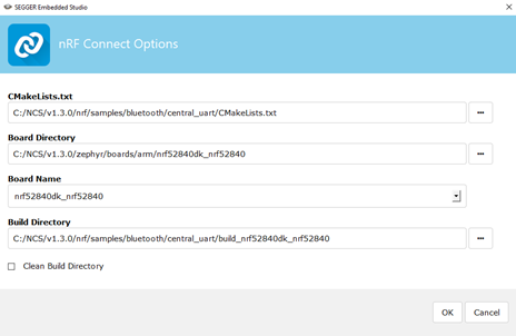
Building and Flashing the Project
If the project opened successfully, you can build the project and flash it to the second Development Kit following the instructions above for the peripheral project.
Testing the Project
To test the communication between the boards, you’ll need a terminal emulator like Putty or TeraTerm. I will be using Putty for this tutorial but you are free to use the one you prefer.
To connect a terminal emulator, you’ll need to find the COM port to which the DK is attached. If you’ve got the nRF-Command-Line-Tools installed, you can simply open a terminal and type:
nrfjprog –com
Here’s what it looks like for me.
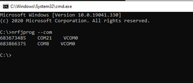
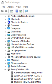
If you don’t have the command line tools installed, you’ll have to use the respective method for determining the COM port for your operating system. For Windows systems, open the Device Manager and look for devices listed under Ports (COM & LPT) as JLink CDC UART Ports. Here’s what it looks like on my Windows PC. It matches what nrfjprog found above.
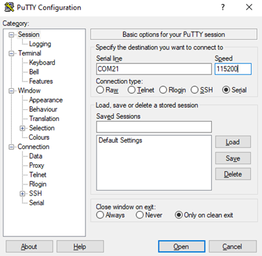
Now that we’ve found the ports, we can connect our terminal emulators to these ports. Open Putty and select Serial connection. Enter the first COM port in the Serial line. Change the Speed to 115200. Click Open. The configuration should look like this:
Now do the same for the second DK.
When the terminals come up, they are likely blank since the application was running before the terminal was started. Hit the Reset button on the Central device and you should get an output like this in your terminal window:
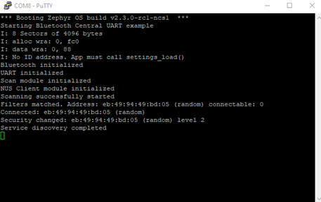
We can see that Zephyr started up, initialized the device, scanned for the peripheral device, found it and connected to it. If we type the word “Hello” in this central device window, we will see it show up in the other terminal window like so:
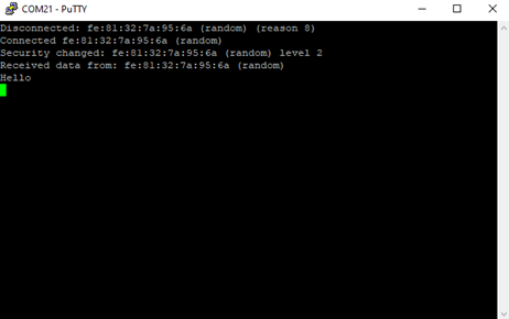
And there you have it! Any data entered on one terminal will automatically be sent to the other device and will appear in the other terminal. You can take this basic functionality and use it to build all sorts of applications.
Testing with the NUS with a smart phone
If you only have one Development Kit, or just want to test with a Smartphone, please follow below. I’m using iOS but there is an equivalent Android app as well. You’ll want to download the nRF Toolbox app for your device from the app store. Also follow the instructions above for connecting a Terminal program to your Development Kit.
Step 1: Open the nRF Toolbox app and UART under “UTILS Services”
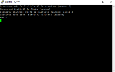
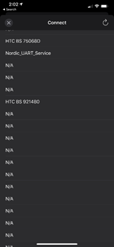
Step 2: Click Connect and find the “Nordic_UART_Service” in the list of devices.
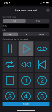
Step 3: Touch one of the squares in the grid and enter the word “Hello” in the box, choose a symbol and hit “Create”
Step 4: Hit your new button and see your text appear in the terminal.
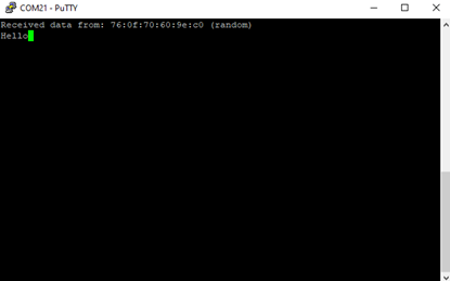
There you have it. You can use this example as the basis for your next application, for testing, or anything you can imagine. I hope you learned a little and find something useful for your next project.


