
This getting started guide is meant as a more detailed practical guide for the Zigbee OTA (Over the Air) Upgrade Client Example found on Infocenter. If you have any questions regarding Zigbee or Zigbee OTA, please create a ticket in DevZone.
You will use the following setup:
- 3 nRF52840 Development Kits
- 1 nRF52840 Dongle (a nRF52840 DK can replace the Dongle)
The hardware will have these tasks:
- 1 DK will run the CLI Agent Router example, this DK will be our Network Coordinator. Hence from now on, this DK will be referred to as the Coordinator.
- 1 DK will run a Client + Bootloader, this is the device we will upgrade the firmware on. Hence from now on, this DK will be referred to as the Client.
- 1 DK will run a Server. This board will be flashed with a server file we generate in step 5. Hence from now on, this DK will be referred to as the Server.'
- The nRF52840 Dongle will be used as a packet sniffer to monitor the network traffic and see that everything goes as planned.
The following tools are required:
- GNU Arm Embedded Toolchain (7 2018-q2-update or newer)
- nrfutil (5.1.0 or newer - pip install nrfutil)
- Terminal Window (PuTTY/Termite/MobaXterm for example)
- Wireshark (installation is explained)
The SDK used for this guide is nRF5 SDK for Thread and Zigbee v3.0.0, which can be downloaded here.
The path to the different parts of the SDK that will be used is:
<InstallFolder>\examples\zigbee\experimental\cli\cli_agent_router (CLI Agent Router example)
<InstallFolder>\examples\zigbee\ota (The Bootloader and Client example)
Let's start by setting up the nRF Sniffer.
Step 1: nRF Sniffer with Wireshark setup.
There is a detailed guide on the Infocenter on how to setup the nRF Sniffer with Wireshark here. Since we are using a nRF52840 Dongle as our sniffer, follow the steps described under PCA10059 Dongle to flash the correct firmware to the Dongle. After flashing the firmware just follow the steps under Installing Wireshark and extcap plugin, Starting Wireshark with the sniffer (select channel 16 instead of 11), and Configuring Wireshark for Zigbee. When you are finished with the configuration, just start sniffing for packets on channel 16. You can also use a nRF52840 DK as the sniffer by following the described steps under PCA10056 Development Kit.
Step 2: Flash the network Coordinator to the first DK
The board that acts as a Coordinator for the network oversees who can join our network. It is always only one Coordinator in a network. The Coordinator also acts as a router and stores security information for the nodes of the network. It is always addressed with the short address 0x0000, as you will see later in the sniffer logs.
In this guide, we will use the CLI Agent Router example as our Coordinator. This example is found in the <InstallFolder>\examples\zigbee\experimental\cli\cli_agent_router folder. You can either compile the example yourself or flash the precompiled .hex-file found in the hex folder. We also need to use a serial terminal in order to type in our CLI commands to configure and start the network. Open a serial terminal with these settings:
- 115200 bit/s
- 8-bit-long word
- no parity
- 1 stop bit
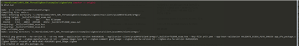
I use a terminal named MobaXterm. In the screenshot below I've flashed the DK with the CLI Agent Router example and opened a serial terminal:
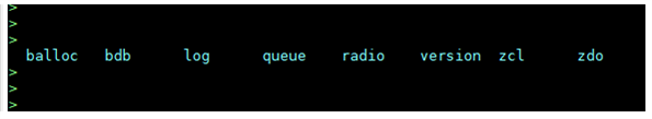
The command options balloc, bdb, log, queue, radio, version, zcl, and zdo appeared when I pressed the TAB-button in the terminal window. In this guide we will only use three of the bdb command options:
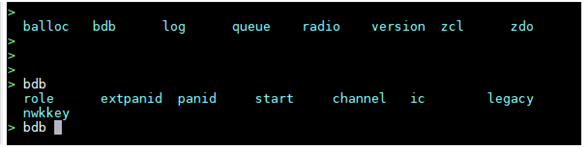
More precisely the options: role, channel, and start.
We will set role to zc which is the CLI command for Coordinator, channel to 16, and start forming our network by typing bdb start. More in-depth details of all the commands available can be found here.
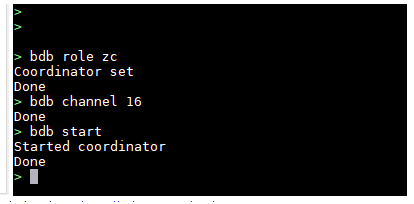
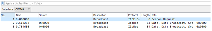
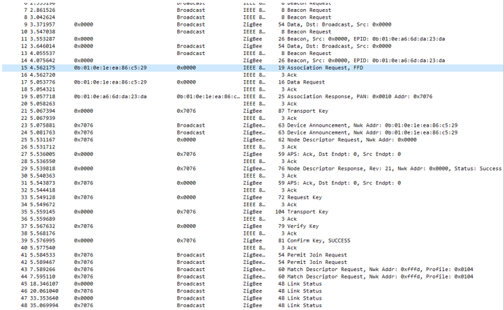
In the picture above I've started the network. I first set the role of this device to be the Coordinator, then selected channel 16, and then started the network. If we look in Wireshark we can now see that this device is now the Coordinator of the network and that it is broadcasting Beacon Request:
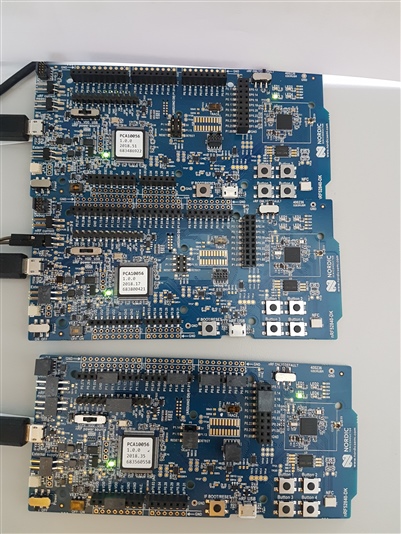
In the picture below you can see that the DK at the top is running as the Coordinator and that LED3 is lit, as expected from the Zigbee BSP LED reference (Node is connected to a Zigbee mesh network).
Let us move on and take a look at the tasks of the Client and Server.
Step 3: Client and Server introduction
As stated in the introduction, we need a Client and a Server in order to do a OTA firmware upgrade.
The Client is the device we wish to upgrade with the new firmware. It is responsible for downloading, installing and rebooting the new firmware with the use of the OTA Cluster. A Bootloader is also needed at the Client, the Bootloader has the task of verifying the integrity of the new image and the installation of the new image.
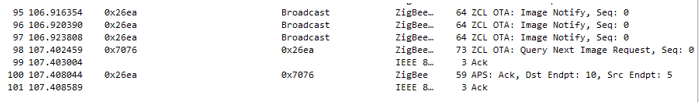
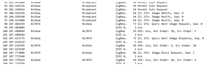
The Server is a device in our network which contains the firmware package we wish to use for our OTA. The Server broadcasts an OTA: Image Notify message out in our network to which the Client response with a query and the transmission of the new firmware starts, as shown in the Wireshark log below. The server has the short address 0x26ea and the client has the short address 0x7076.
Note that these two addresses are chosen when the two devices join the network. The addresses you see in Wireshark might not be the same since this is a random process. It is only the Coordinator that has the fixed address 0x0000.
Let's start by creating a script for the firmware needed on our Client DK
Step 4: Client
The first thing we need to do is to navigate to the ota folder, located in <InstallFolder>\examples\zigbee\ota.
We will start by generating cryptographic keys that we are going to use for signing our OTA packet, the client, and the bootloader. Read more about keys here.
Open a command prompt window in this folder and run the two commands:
nrfutil keys generate priv.pem
nrfutil keys display --key pk --format code priv.pem --out_file dfu_public_key.c
We need to move and replace the output file of the second command, dfu_public_key.c, with the existing file found in the <InstallFolder>\examples\dfu folder.
The next step is to create a batch script or a shell script, dependent on which OS you are working on. Paste the following commands into your script file:
make -j -C bootloader\pca10056\blank\armgcc
make -j -C client\pca10056\blank\armgcc
nrfutil settings generate --family NRF52840 --application client\pca10056\blank\armgcc\_build\nrf52840_xxaa.hex --application-version 0x01010101 --bootloader-version 1 --bl-settings-version 2 --app-boot-validation VALIDATE_ECDSA_P256_SHA256 --key-file priv.pem settings.hex
mergehex -m client\pca10056\blank\armgcc\_build\nrf52840_xxaa.hex settings.hex -o dfu_client.hex
nrfjprog -f nrf52 -e --snr 683118922
nrfjprog -f nrf52 --program mbr_nrf52_2.4.1_mbr.hex --chiperase --snr 683118922
nrfjprog -f nrf52 --program bootloader\pca10056\blank\armgcc\_build\nrf52840_xxaa_mbr.hex --snr 683118922
nrfjprog -f nrf52 -r --program dfu_client.hex --sectorerase --snr 683118922
(I named my batch script dfu.bat)
You must change the serial number (--snr) to the number written on the board you wish to use as a client. You also need to copy the MBR .hex-file to the ota folder. The .hex-file is located in the <InstallFolder>\components\softdevice\mbr\nrf52840 folder.
The interesting thing to look at in this script is the application version used to generate the bootloader settings page. This number should match the number for the define OTA_UPGRADE_TEST_FILE_VERSION in the main.c file for the client. You will have problems the second time you try to upgrade the client if these numbers do not match because the bootloader will not understand that a new firmware is available due to the two numbers being different. The firmware will be discarded.
Save and close the file, we will run this script in the test section of this tutorial.
Step 5: Server and firmware packet
The firmware we are going to use on our Server is generated when we generate the Firmware packet.
Create a batch script or a shell script, dependent on which OS you are working on. Paste the following commands into your script file:
make -j -C client\pca10056\blank\armgcc
nrfutil pkg generate --hw-version 52 --sd-req 0x00 --application-version 0x01020101 --application client\pca10056\blank\armgcc\_build\nrf52840_xxaa.hex --key-file priv.pem --app-boot-validation VALIDATE_ECDSA_P256_SHA256 app_dfu_package.zip --zigbee True --zigbee-manufacturer-id 123 --zigbee-image-type 321 --zigbee-comment good_image --zigbee-ota-hw-version 52 --zigbee-ota-fw-version 0x01020101
(I named my batch script dfu2.bat)
Notice that the application version is different for the new client firmware that is generated. Save and close the file, we will run this script in the test section of this tutorial.
Step 6: Test procedure
Make sure that the nRF Sniffer is still running and logging. The logs give valuable information about the network traffic.
Power on the Client and Server DK and run the script you created in Step 4 first to build and flash the bootloader, client, and MBR to the Client.
As you can see from the script, it will build the client and bootloader example, generate a bootloader settings page for the client example, merge the settings page with the client example. It will then erase the board, flash the MBR, bootloader, and the client example + settings page.
Here is my output:
The next step is to run the script from Step 5, but before running the script we must modify the main.c file for the client. It is in the <InstallFolder>\examples\zigbee\ota\client folder.
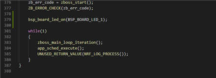
There is one thing that must be modified, and that is increasing the application version. The application version is as previously stated, given by the definition OTA_UPGRADE_TEST_FILE_VERSION. Let us change it from 0x01010101 to 0x01020101. We can also add a LED so that we see that the upgrade was successful, by adding the line bsp_board_led_on(BSP_BOARD_LED_1); before the while-loop in main(), like this:
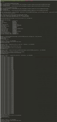
Save the main.c file and run the second script, this is my output:
Finally, we need to connect the two DK’s to our network. We started our network in Step 2, but the CLI Agent Router example is configured to allow devices to join for 180 seconds after the start command is executed. We must execute the start command again so that our devices can join the network. Type bdb start. You will now see in Wireshark that the Coordinator starts to broadcast and that the Client sends an association request to the Coordinator, the Coordinator responds with an acknowledgement and the association procedure continues until the device is authenticated (from line 15 to 41).
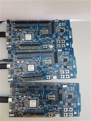
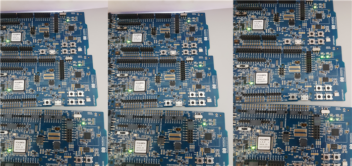
Below is a picture of the three boards after the Client has been programmed to the board at the bottom, and it has joined the network since LED3 is on.
The next step is to flash the Server firmware to the last DK. This is done by running the following command in a Command Prompt window:
nrfutil dfu zigbee -f 007B-0141-01020101-good_image.zigbee -snr 683194832 --channel 16
Note that you need to select the correct serial number for your device (change -snr 683194832).
The device will then join the network the same way as the client did:
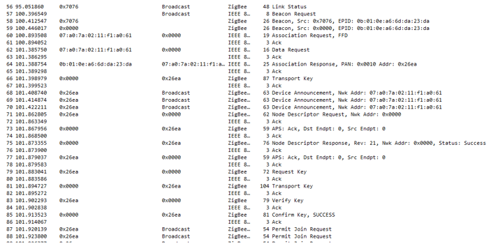
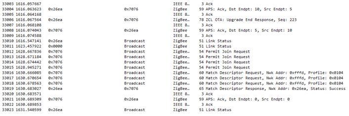
After the server has joined the network it will broadcast an OTA: Image Notify message to all surrounding nodes that the server has new firmware available. The Client responds (line 98) with an OTA: Query Next Image Request message and the OTA procedure starts.
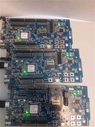
Below is a picture of when the Server has joined the network and the OTA update process is started, the Server is the board in the middle:
When LED3 and LED4 are lit on the Server, the broadcasting of the new firmware starts. LED4 on the Client board will alternate between on and off during the update process.
This update took 26 minutes and 25 seconds to finish, 32928 packets were sent back and forward. The packet number includes actual data packets, link status, and acknowledgement packets.
As you can see from the picture of the boards below, the Client DK now has BSP_BOARD_LED_1 lit on (LED 2) after the update finished.
Sniffer logging of the process can be downloaded here: 4617.Sniffer Logging OTA.zip
Unzip the file and open it in Wireshark.
Troubleshooting:
Issues joining the network:
- Do all the devices have the correct channel set up?
- Can you see that the Server is broadcasting in Wireshark?
- Do a memory erase on all devices, delete all generated .hex-files and the firmware package, and start from Step 2.
Issues with upgrading the firmware:
- Is the version number correct?
- Does the new Application run smoothly on another DK?
- Are the correct keys used?
- Is the correct app-boot-validation used?
If you have any questions regarding Zigbee or Zigbee OTA, please create a ticket in DevZone.
