This post is older than 2 years and might not be relevant anymore
More Info: Consider searching for newer posts
This discussion has been locked.
You can no longer post new replies to this discussion. If you have a question you can start a new discussion

Please help me understand the oscillescope reading of my NRF24L01

Hi everyone. I am working on a project while doing my undergrad in EE and am confused on a few things.

I am using Raspberry Pi 3s with the NRF24L01 (NRFL) chip and code from here to transmit data back and forth and I want to get deeper into the chip to see how it's working. (note that I set up my own tx and rx files and did not use the example tx/rx code at the link)

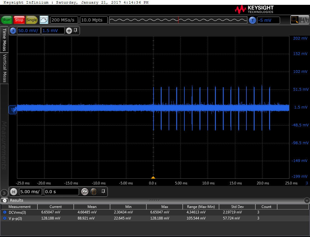
To do this I stuck an antenna on my scope and transmitted "A B C D". I'm having difficulty understanding the output. I'd like to be able to trace the package being sent down to the specific bit. DKtest3Pic.png This image is a picture from the scope. I'm sampling the NRFL tx signal at 200Msps with a tx speed of 2Mbps. First, I don't understand why there are 16 bars. When I captured this picture I had no downtime on the tx chip, so it's my understanding that these 16 bars represent an entire package. I also think this because the view on the scope was 16 bars repeating and every so often there was a larger space in between chunks of 16.

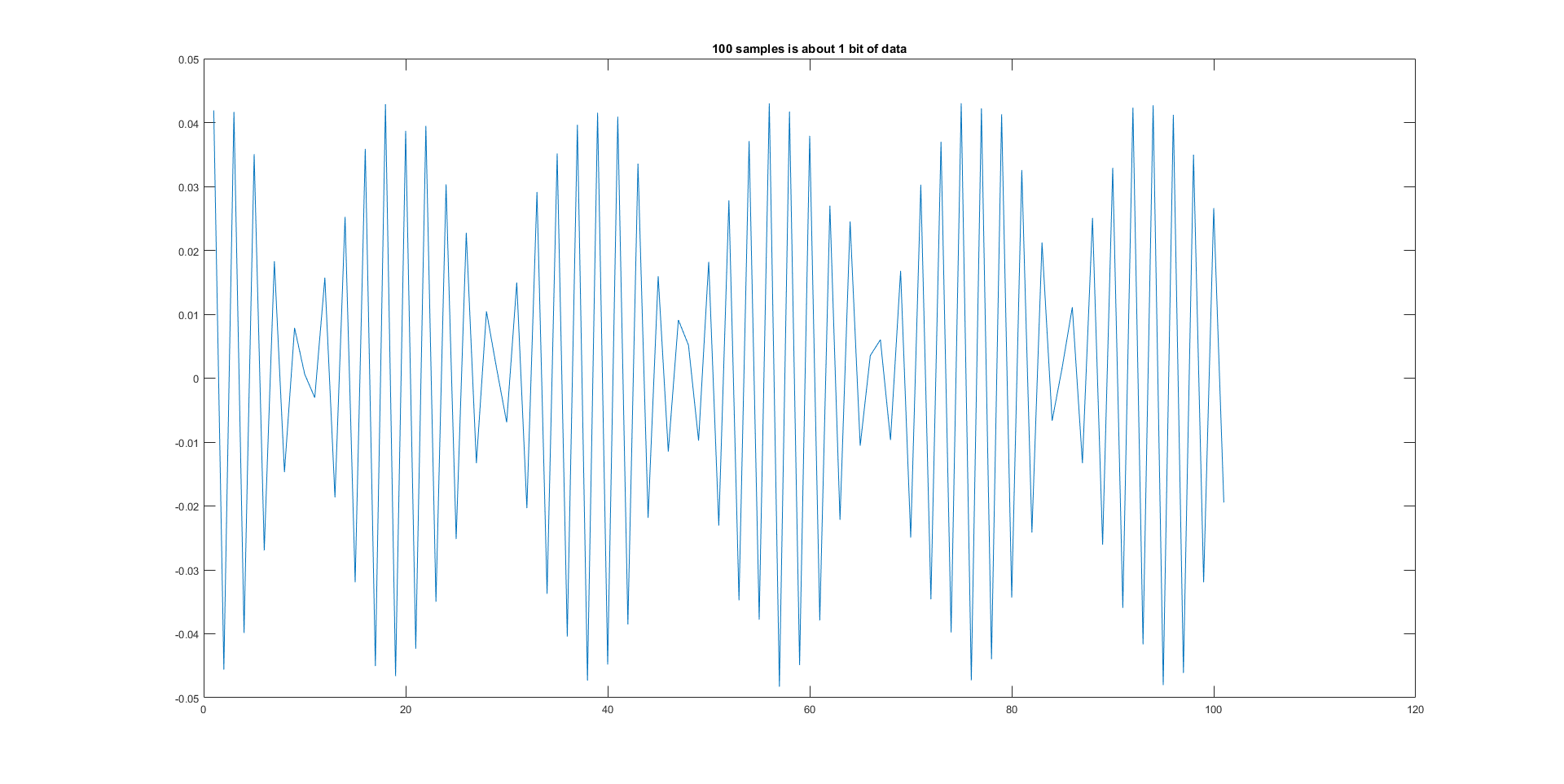
However, my math says that this should be about 100 samples/bit, as in this image. 1bit.png but when I zoom in on one of the 16 bars to see how many samples/bar, there are 18k=180bits=22.5 bytes.

I don't understand this. According to the data sheet of the NRFL, the max package size total is about 40 bytes and from what I can tell I didn't change the number of re-try sends. Unless the default on the chip is 15 retries, I'm not sure whats going on. If a tx is just one of the aforementioned bars, that's still an odd number of bytes-22.5?

Any help would be greatly appreciated!!

  • Attaching a scope to the antenna is not going to give you useful data

    For a start, the nRF24 transmits on 2.4Ghz (thats 2400 Mhz), and its unlikely that the scope you have will get anywhere close to being able to resolve that frequency, unless its a very specialist piece of equipment.

    In addition to that, the nRF24 is unlikely to just transmit the exact data you sent to it. The data is encoded into the nRF24's data protcol which will have all sorts of other data in it which is sent

    On top of that you'd have to decode the modulation method used by the nRF24 etc etc

    I'd recommend you fully read all the available documentation on the nRF24 before you continue.

    Edit.

    Based on your feedback, I'd recommend you checkout this link

    www.rtl-sdr.com/.../

    I think its a better solution to what you are trying to achieve than using a scope

  • The scope I'm using can go up to 13GHz. It's being used for milimeter wave research so I know it can get the waveform.

    I know the nrfl uses other data. I've read the packet extensively, all 78 pages of it. I know the format of the packet that's sent. It uses GFSK which isn't terribly complex but decoding that modulation is something I'll look into/didn't think about.

  • Wow

    13Ghz Scope, you must go to a high class university ;-)

    I presume you have the correct matched connections for the scope to connect to the antenna impedance of the nRF24.

    I don't know much about the nRF24's RF modulation, but it may also employ frequency hopping like BLE does, which will make things even harder to decode. (well, if you are just tapping into the antenna, and don't have any other RF signal interference then I wideband receiver would suffice.

    I presume the data is also encrypted.

    Edit. See my updated answer for another approach

  • Ha, well, my prof is doing some big research so he doesn't seem to have a problem getting grants. It's not a univesity/lab scope, it's one specifically for his research project(s). Yes, we matched the antenna. And there is WiFi running around but the output of the NRFL has 4 possible levels, so I set it to max level (0 dBm) and we stuck the NRFL right ON the antenna to maximize SNR.

    I don't know that I actually need to decode it though? Maybe I'm looking at this part of the project all wrong. I thought that I would be able to count the times the frequency increased/decreased and see exactly where in the transmission my message was being sent. But it sounds like this may no be possible.

    A quick look at the main site the link you sent me to says that I am not looking at this in the correct way. Not gonna be fun to tell my prof this. :/ Thank you for your help!

  • No worries.

    Please accept the answer if you think its useful, otherwise it remains open and Nordic have to close it themselves (manually)

    Good luck with your project.

    I hope your professor understands when you tell him your initial hypothesis and method was possibly not correct and that you need to investigate this another way.

Related