This post is older than 2 years and might not be relevant anymore
More Info: Consider searching for newer posts

SWD JTag to a Sparkfun nRF52832

Hi

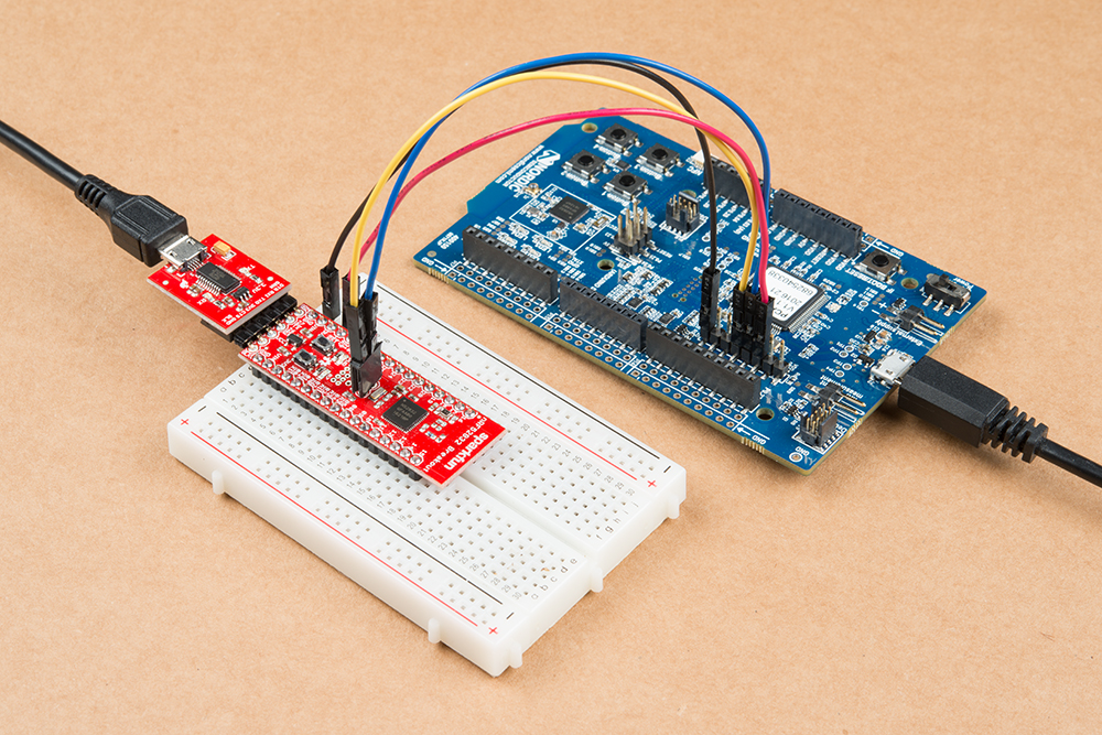
I have gotten a Nordic PCA10040 hooked up to a Sparkfun nRF52832 as described near the bottom of the page here: learn.sparkfun.com/.../nrf52832-breakout-board-hookup-guide (Resources and Going Further).

I have also got a working build environment and debugging working using Eclipse and the GNU Arm Eclipse Plugin via this tutorial (which BTW was incredible helpful). I am able to build, deploy and debug.

What I would like to do is be able to build, deploy and debug on the Sparkfun breakout board listed above. Are there any tutorials regarding this ?

Thanks

J

  • I'm not aware about any tutorial, but if you are able to attach JTAG/SWD cable from P20 header of nRF52 DK (PCA10040) to right header/pins of Sparkfun board then all the examples and development should work exactly as you would run it on nRF52 chip on PCA10040. What is the error you see when you try it? The only thing which will be then needed is to check LF clock source (does Sparkfun board have 32kHz crystal?) and to do your custom header file and reference it in example projects instead of pca10040.h (there is quite nice hook in boards.h where you define custom board header in your project and change define which goes to the compiler&linker from Make file or project file (depending if you use GCC + Make or Keil or IAR or whatever else...) But that might not be needed for BLE only examples (unless you expect debug/logging UART and LEDs/buttons to work).

    Edit:

    I've seen the picture and guide at Sparkfun, I believe you have done it correctly. You will never work in the way that you would see multiple targets, nRF52 DK will always look the same in nrfjprog or nRFgo Studio (or SEGGER tools or anything else you use). The magic happens inside auxiliary MCU on PCA10040 (that big Atmel chip with white sticker on it;) which runs SEGGER J-Link OB. That has 3 possible targets and simple cascade before every command (incoming over USB) will decide if it targets thing on P20 or P19 or on the PCA10040 internally. This post says more. So you should try to flash it and if there is no error just make sure it really detected GND and VDD/VTG from Sparkfun target (so the FW is now on that instead on nRF52832 chip soldered on PCA10040). If it doesn't detect Sparkfun board then try this.

    Few more external blog posts about how to handle VTG, VDD and GND Detect PINs on P20 header of nRF51 or nRF52 DK boards are here and here, also several Q&Aa on this forum e.g. here and here.

  • Hi

    Thanks so much for your reply.

    Here is what the Sparkfun blog post states to do with the following photo:

    image description

    It states to "(The nRF52832’s single-wire debug – SWD – pins are broken out to test points near the NFC antenna pads – labeled “C” and “D” for SWDCLK and SWDIO.)"

    So I have soldered on some female headers to the "C" and "D" ports on the Sparkfun board. According to the above, I am then to connect them to SWDCLK and SWDIO.. Are you saying this isn't correct ?

    As for what I am getting, when I run JLinkExe I only see the Nordic board. I can't see how to get access or connect to the Sparkfun board.

    Thanks!

    J

  • Cannot fit into comment, updating my answer;)

  • Hi Thanks so much for the answer.. I think I have bricked the sparkfun board. It doesn't seem to be responding anymore. So I have ordered a couple more. But I think you are right. When I flash the Nordic board with the SWD cables attached, it does not flash the Nordic board. When I disconnect the cables, it does. So that appears to be working. But as I said, the Sparkfun board isn't responding. So I will have to wait for the replacement.

    Thanks again

  • I don't think that picture makes much sense: it has two debug probes attached to the same target 1) the Sparkfun probe board on the extreme left and 2) the NRF52DK probe on the right half of the board on the right. Wouldn't both probes fight over the target? After all, as the Sparkfun tutorial suggests, you are SUBSTITUTING a more powerful probe (the NRF52DK) for the less powerful Sparkfun one. But maybe the Sparkfun board is just providing power to the target. I would suggest: 1) eliminate the Sparkfun probe 2) use 4 jumpers as shown 3) ALSO power the target to 3V say using a battery wired to your breadboard (the jumpers don't power the target, but the target must be powered.) Also, exactly how do you know which board JLink is programming? AFAIK it does not announce on its console any identifier of the mcu instance (or radio MAC), only the model number of the board e.g. nrf52832.

Related