This post is older than 2 years and might not be relevant anymore
More Info: Consider searching for newer posts

I2S does not work as expected on nRF52832

Hello,

some time ago I was struggling with interfacing an I2S microphone with the nRF52832. That remained unsuccessful. My conclusion back then was that the selected I2S microphone and the nRF52832 were incompatible (the mic wanted 32-bit word size, which the nRF did not support).

In a current project, I -again- need to interface an I2S device to A/D convert the analog data from a MEMS microphone. This time a WM8731 codec, which is known to be very versatile and universally interfaceable. Since the WM8731 specification states that it supports different word lengths (16, 20, 24, or 32 bit), I was very positive that it can be used with the Nordic chip.

It seems I was wrong.

I took a small test board consisting of the WM8731 and the most necessary external components as recommended by the manufacturer and connected it with a Knowles analog MEMS microphone. This setup works flawlessly with a SAM4L development board.

With the Nordic nRF52 development board (PCA10040, v1.1.0) and the latest SDK (v13.0) the TWI communication (for setting up the codec) works and the codec also starts providing the samples over I2S, but I only see scrambled data in the Nordic's I2S buffers. I double and triple checked all my methods as well as the clock and codec configuration - they should work, but they don't.

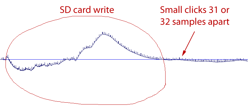
I also played with different bitstream formats, which both sides (the codec and the nRF52) "speak". I made some recordings with a 1 kHz sine as input. Here are the results:

REC_I2S.wav

REC_LEFT-ALIGNED.wav

REC_RIGHT-ALIGNED.wav

As for the recording, I write the data from an intermediate buffer to an SD-Card (based on the SD-Card example). This uses SPI (and EasyDMA). Some parts of the recordings sound like as if the SPI and the I2S transfers would disturb each other. I hope that is not true.

I also tried different MCL speeds (4, 8, 10.6, 16 MHz), different left-right-clock ratios (CONFIG.RATIO), bit-depths (CONFIG.SWIDTH), but nothing works right. If the recording sounds fine for 50 ms, then it gets totally distorted right after that (as if the sync between nRF52 and the codec would be gone).

Here is a simple question to the crowd out there: did anyone manage to interface any audio codec that works perfectly with the nRF52832?

If yes, please tell me which codec it was and what settings worked.

If not, I am tempted to believe that the I2S interface of the nRF52832 is buggy and hence useless.

  • Hi, I managed to set nRF52832 working on custom PCB with MAX98357A Class-D amplifier connected over I2S and it works very well. Might not be 100% relevant as you have opposite use case (I2S as input to nRF52) but I would double check:

    • What exact coding on 3-wire interface is configured in your A2D (they typically support I2S, Left-justified and TDM, all with Mono or Stereo, different bit resolutions and different sampling frequencies = in total easily 10-20 configurations leading to "noise" decoding if not aligned on both sides).
    • Observe 3-wire interface with logical analyzer and try to decode it manually to confirm it's exactly what it should be.
    • Double check if you are not affected by one of three I2S anomalies existing on nRF52832 Rev 1.

    Sample recordings with monotone signal (or is it just background noise?) you provide are not helping much but if I understand it correctly it works, there are just some crackling noise cuts. Are you sure that you have correctly implemented both I2S input and SPI output with at least two DMA buffers which make sure that while one is being read the other is being sent over SPI? I managed to get pretty nice opposite application (reading over SPI from external flash and playing over I2S) but it was little flaky when there was heavy BLE activity (because even with 100-250B buffers in "swing" implementation you need to have some computing time to shift the indexes so if you are blocked for longer period then is one of your I2S input/SPI output blocks you can see crackling effects similar to what you present here).

  • Hi,

    thank you very much for the quick reply! I am happy to hear that I2S of the nRF52 worked for you! :) The two main differences I see are a) the direction of the stream (Nordic->Codec in your case) and b) no need of an MCL with the MAX98357A.

    Regarding your points to double check:

    • I use a 2-wire interface (TWI) to set up the codec. I already checked it and the TWI part works perfectly.
    • I am not affected by the currently listed I2S anomalies.
    • I already tried various formats, bit depths, mono and stereo, and sampling frequencies, which both sides (Nordic and Codec) support, but no success.
    • My buffers are large enough and handling is OK.

    Next week I will have access to a 4-channel oscilloscope and I will have a closer look on the I2S stream. Until then I may try to use the codec to play back something from the nRF52 and see if that direction works.

    Thanks again, Tamas

  • Hello again,

    after much invested time I came to the conclusion that the WM8731 I was using was damaged! I don't know when and how it happened, but after swapping the codec, things worked better.

    So at this point I'd like to formally apologise for my previous assumption that the I2S interface of the nRF52 would be useless. (Whether it is buggy or not, I am not sure yet.)

    I am now able to record over line-in through the WM8731, when the nRF52 is master. I used the following setup:

    #define TWI_frequency     NRF_TWI_FREQ_400K
    
    #define I2S_BUFF_LENGTH 512
    uint32_t m_i2sBuffer[I2S_BUFF_LENGTH]= {0};
    
    nrf_drv_i2s_config_t const I2S_config=
    { 
      .sck_pin      = (uint8_t) PIN_I2S_SCK,
      .lrck_pin     = (uint8_t) PIN_I2S_LRCK,
      .mck_pin      = (uint8_t) PIN_I2S_MCK,
      .sdout_pin    = (uint8_t) NRF_DRV_I2S_PIN_NOT_USED,
      .sdin_pin     = (uint8_t) PIN_I2S_SDIN,
      .irq_priority = (uint8_t) APP_IRQ_PRIORITY_LOW,
      .mode         = (nrf_i2s_mode_t) I2S_CONFIG_MODE_MODE_Master,
      .format       = (nrf_i2s_format_t) I2S_CONFIG_FORMAT_FORMAT_I2S,
      .alignment    = (nrf_i2s_align_t) I2S_CONFIG_ALIGN_ALIGN_Left,
      .sample_width = (nrf_i2s_swidth_t) I2S_CONFIG_SWIDTH_SWIDTH_16Bit,
      .channels     = (nrf_i2s_channels_t) I2S_CONFIG_CHANNELS_CHANNELS_Left,
      .mck_setup    = (nrf_i2s_mck_t) I2S_CONFIG_MCKFREQ_MCKFREQ_32MDIV8,
      .ratio        = (nrf_i2s_ratio_t) I2S_CONFIG_RATIO_RATIO_128X
    };
    

    The above gives me 31250 Hz, 16 bit, mono recording. This is how I set up the codec:

    wm8731_reset(&m_twi);
    wm8731_set_master_or_slave_mode(&m_twi, 0);           // set codec to be slave
    wm8731_power_mode_all_active(&m_twi);
    wm8731_set_sampling_control(&m_twi, 0, 0, 7);         // normal mode, BOSR=0, SR=[0,1,1,1]
    wm8731_set_digital_audio_interface_format(&m_twi, 2); // I2S
    wm8731_set_digital_audio_data_bit_length(&m_twi, 0);  // IWL_16_BIT
    wm8731_adc_input_select(&m_twi, 0);                   // select Line-in
    wm8731_left_line_in_volume_set(&m_twi, 0x1F);         // max input volume
    wm8731_right_line_in_volume_set(&m_twi, 0x1F);        // max input volume
    wm8731_set_left_line_in_mute(&m_twi, 0);              // unmute
    wm8731_set_right_line_in_mute(&m_twi, 0);             // unmute
    wm8731_enable_adc_high_pass_filter(&m_twi, 1);        // enable HPF
    wm8731_set_active(&m_twi, 1);  
    

    And this is how I start I2S:

    nrf_drv_i2s_start(m_i2sBuffer, NULL, I2S_BUFF_LENGTH, 0);
    

    Now, I have some comments on the I2S driver. According to the documentation, it splits the pointed buffer into two halves and uses them as ping-pong buffers. Then the documentation says, the last parameter of nrf_drv_i2s_start() is "Size of the buffers (in 32-bit words)." For me it is ambiguous: does it mean the size of each buffer or the total size of the buffers? It turns out, it means the total size.

    The next surprise was, that the I2S handler seems to deliver the contents of the sample buffers in a (for me) unexpected order. What I mean is, if the input audio can be split into a sequence of buffers "A,B,C,D,E,F,...", then I get the buffers from the I2S handler in this order: "B,A,D,C,F,E,...". (I really think that I did not mess up things here myself ...)

    This is an example recording:

    REC_0092_TheKyotoConnection-Hachiko.mp3 (From freemusicarchive.)

    At first it sounds okay. No clicks at buffer edges, i.e., buffers of samples are transferred OK.

    But if you look at the samples more closely OR if you look at recordings where the input was muted, you will see that there are two problems:

    • Every 31st or 32nd sample (alternating, and this is NOT aligned with buffer sizes) is superimposed by a small click, which leads to a 1000 Hz (+harmonics) overlay.

    • Every writing to the SD card can be seen (and heard) in form of a low-frequency (as compared to the 1000 Hz one) distortion.

    Waveform

    Samples are here (to be viewed as waveform):

    Here are some facts about these distortions:

    • SPI priority (SD card) makes no difference
    • SPI speed (SD card) makes no difference (tried 2, 4, and 8 MHz)
    • Enabling or disabling EasyDMA for SPI makes no difference
    • Bit depth (16 or 24 bit over I2S) makes no difference
    • I2S clock (i.e. sampling rate) makes a difference: doubling the sampling rate doubles the distance between clicks
    • I2S buffer size makes no difference (tried: 64, 128, 256, and 512 32-bit words)
    • I added all relevant external components (mostly capacitors) as recommended, but they also make no difference.

    Can anyone suggest a fix to get rid of the distortions?

    Thanks, Tamas

  • Hello newtom

    I apologize for the late reply

    The fact that the 1kHz noise is not affected by any of the changes you make leads me to believe it is caused by either the power supply, or possibly something on a timer running with a 1ms interval. How have you powered your system? If you are powering it through USB, I would like you to try and switch to a battery, or at least a more clean running power supply, and see if that clears up the noise. If it doesn't, see if you have any timers running, or if anything with a high current consumption triggers (i.e. the radio), with a 1ms interval.

    It would also be interesting to know if the distortions are present on the data sent from the Codec, or if it is generated on being received at the nRF. If you could use a logic analyzer and look at the data outputted from the codec that could be helpful. As for the SD-card noise, are the pins you use for the SPI and I2S close to each other?

    Best regards

    Jørn Frøysa

  • Hi Jørn,

    thanks for the reply. We are still checking this problem - but with rather low priority. I will get back to you soon.

    Tamas

Related