
Story and Official Code Test Passed
I am trying to integrate BLE into Smart-Lock and LoRa Terminal. So I build a custom board with off-the-thelf modules to evalute and integration. In both projects, nRF51822 may connect to a host micro via UART.
As I metioned in anther thread here. It is wired that nRF51822 uart TXD seems running at wrong baudrate. Nordic team suggested me to try latest SDK, I did this morning. Here is my log.
- Download the SDK-v12.3.0, unzip it ;
- Update softdevice to s130_2.0.1.hex inside nRF51822-QFAC with OpenOCD/ST-LINKv2;
- Open MDK5 project located in
**C:\Nordic\nRF5_SDK_12.3.0_d7731ad\examples\ble_peripheral\ble_app_uart\pca10028\s130\arm5_no_packs** ; - Build and program firmware into nRF51822 application flash with ST-LINKv2, bring up debugger;
- Running Nordic_toolbox in Android phone ;
- Scan, Connect to Nordic_UART device ;
- Define custom keypad with strings ;
- Set breakpoint inside MDK5 debugger
- Press keypad, breakpoint hit, and strings received are verfied correctly.
Everything is running OK for official project ! That proves ST-LINKv2/OpenOCD/MDK5 can work and debug as a complete toolchain.
Custom Code UART Baudrate
So I moved on.
- Clone PCA10028.h and rename it to custom_board.h in the path of
C:\Nordic\nRF5_SDK_12.3.0_d7731ad\components\boards ; - Change PIN definitions in custom_board.h ;
- Change Preprocessor Symbols, rename BOARD_PCA10028 to BOARD_CUSTOM ;
- Rebuild project, download, bring up debugger ;
- Open TeraTerm Serial session, identified UART as COM8 in PC, in baudrate 115.2kbps ;
- Scan, connect to device, successful ;
- Press keypad, strings print to TeraTerm are rabbish strings,
Actually, I have solved some other issues such as device can not detected, and wrong TXD/RXD. Now the final UART doesn't work well anyway. We can remove suspects from following items:
- SDK not up to date;
- Toolchain, proved in official code flow;
- TXD/RXD, set HWFC to false, and PIN pairs are correct;
- Xtal,since 16MHz is used for whole system, it should be OK.
Next Step ?
Since the code/flow/toolchain/connections are correct, I have to check if there is any hardware related issues.
My UART definitions are:
#define RX_PIN_NUMBER  4
#define TX_PIN_NUMBER  2
#define CTS_PIN_NUMBER 22
#define RTS_PIN_NUMBER 3

#define HWFC           false
**Is there any cautions for custom GPIO for UART ? or any support circuit requirements ? ** If necessary, I can cut the wire and connect to anther GPIO.
Actually I have done and passed a local loop test for USB/UART, by short circuit TXD/RXD to double check if it is OK in a console terminal. In order to test that, firmware is removed first. And in TeraTerm, every char I entered can be displayed without local echo. So USB/UART works fine.
And I will use another micro to test the nRF51822 UART as close as possible to check if there is some noise nearby. Maybe I will use oscilloscope and logic analyzer for touble shooting.
However things doesn't get better in my project.
Attachements
In order to allow people to have an overview, I shared my schematics/PCB here.
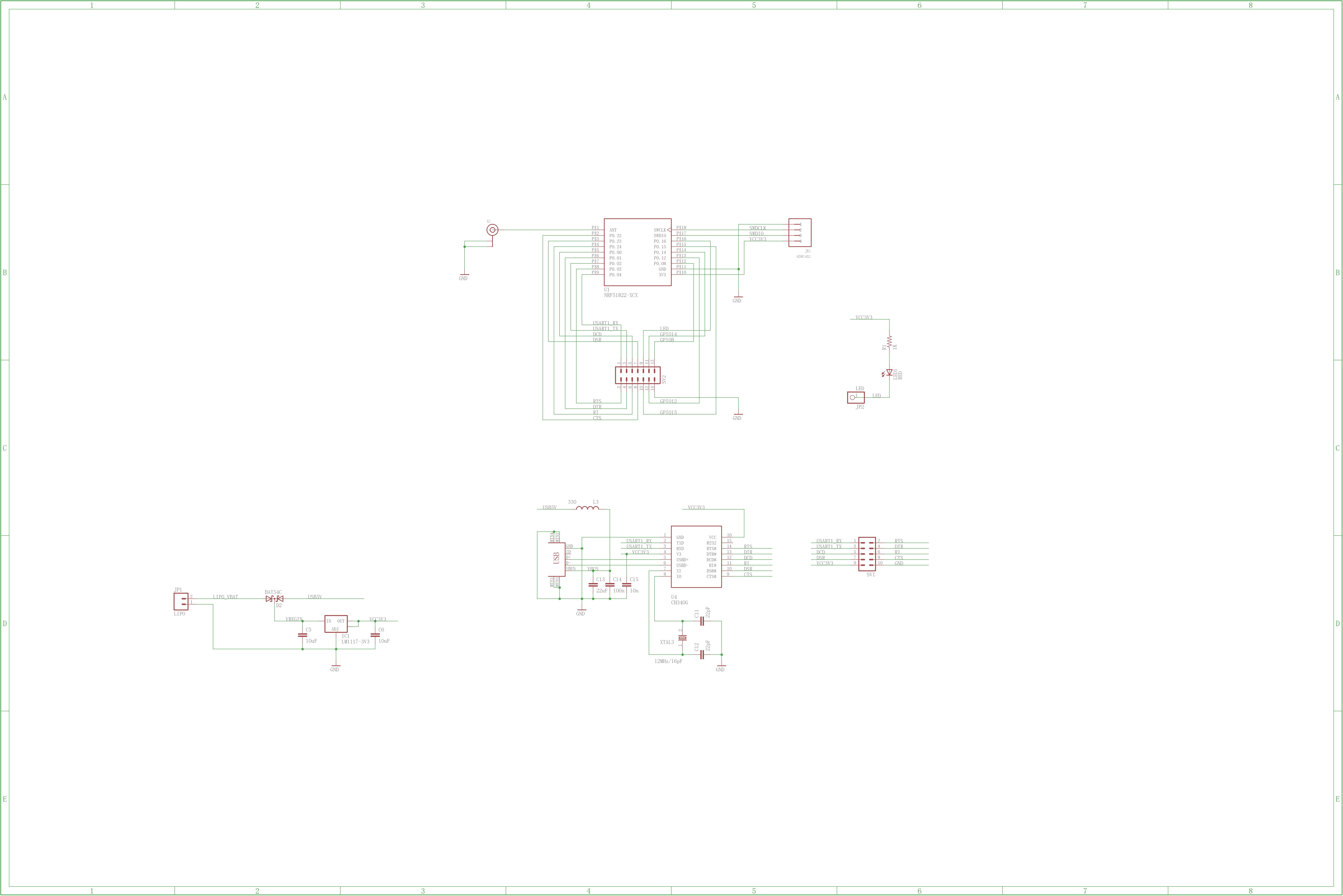
Fig1: Schematics. A simple circuit to connect nRF51822 to CH340G, powered by 3V3 LDO.
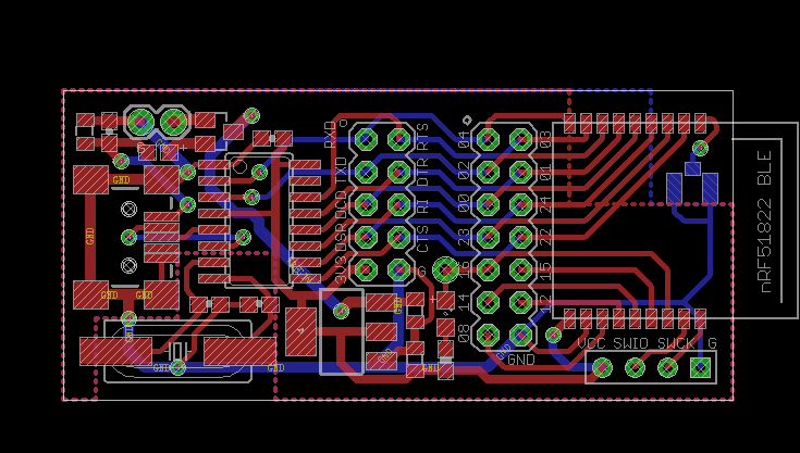
Fig2: PCB, 2 layer, with copper pour
File1: custom_board.h
UPDATE 01
Today I have done some more labs as cross-checking.
- Replace RXD/TXD to another GPIO
- Try barematel peripheral demos without BLE stack, aka. softdevice.
The first lab result is as same as current GPIO definitions. So it seems nothing to do with RF module layout issue, since it is not a problem happens on specific GPIO.
The second lab doesn't print any chars at all.
I have ordered another RF modules for nRF51822 and nRF52832. Unfortunately, P0.10/P0.11 of nRF51822 is short circuit somethere in the module, while nRF52832 is good. So at lease I have to define CTS to another pin to test the official code. I will update this thread ASAP.
UPDATE 02
Well, since my new RF module has fanned out most of the GPIOs, so I can download the original project and modify the code for specific applications. I started from baremetal GPIO blinky, then baremetal UART, finally BLE UART. During these steps, I identified one issue for wrong silkscreen, so I corrected my pinout, then I identified the HWFC definitions in firmware, so I updated the source code anyway. And it think MDK5 register view window is quite helpful during my debug. Thanks to register window, I can confirmed that GPIO and UART are working well or not.
However, after confirmation in my new breakout board, I will go on to test it on my old custom board to check if there is anything wrong with schematics or PCB layout.

