This post is older than 2 years and might not be relevant anymore
More Info: Consider searching for newer posts

ERROR when programming my custom pcb with NRF51288 DK PCA10028

Hello everyone, I've been trying to solve this problem for several days.

Hello everyone, I've been trying to solve this problem for several days. I have developed a custom-built PCB based on the NRF51288 chip but I can not use the NRF51 DK evaluation kit to program through SW DEVICE.

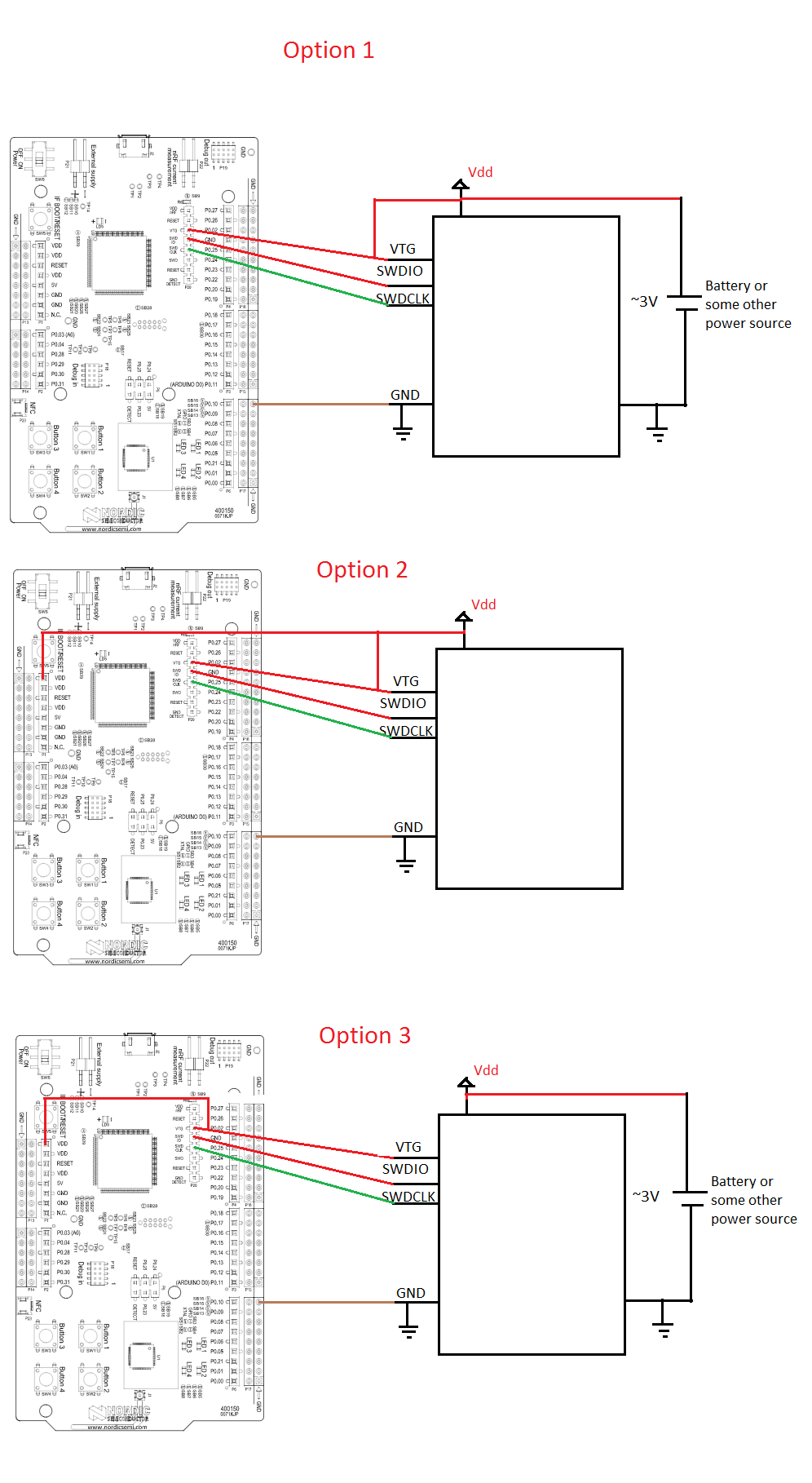
I make the following connection: vteg -> vbat (target) SWDIO -> SWDIO (target) SWDCLK -> / SWDCLK (target) GND -> GND (target)

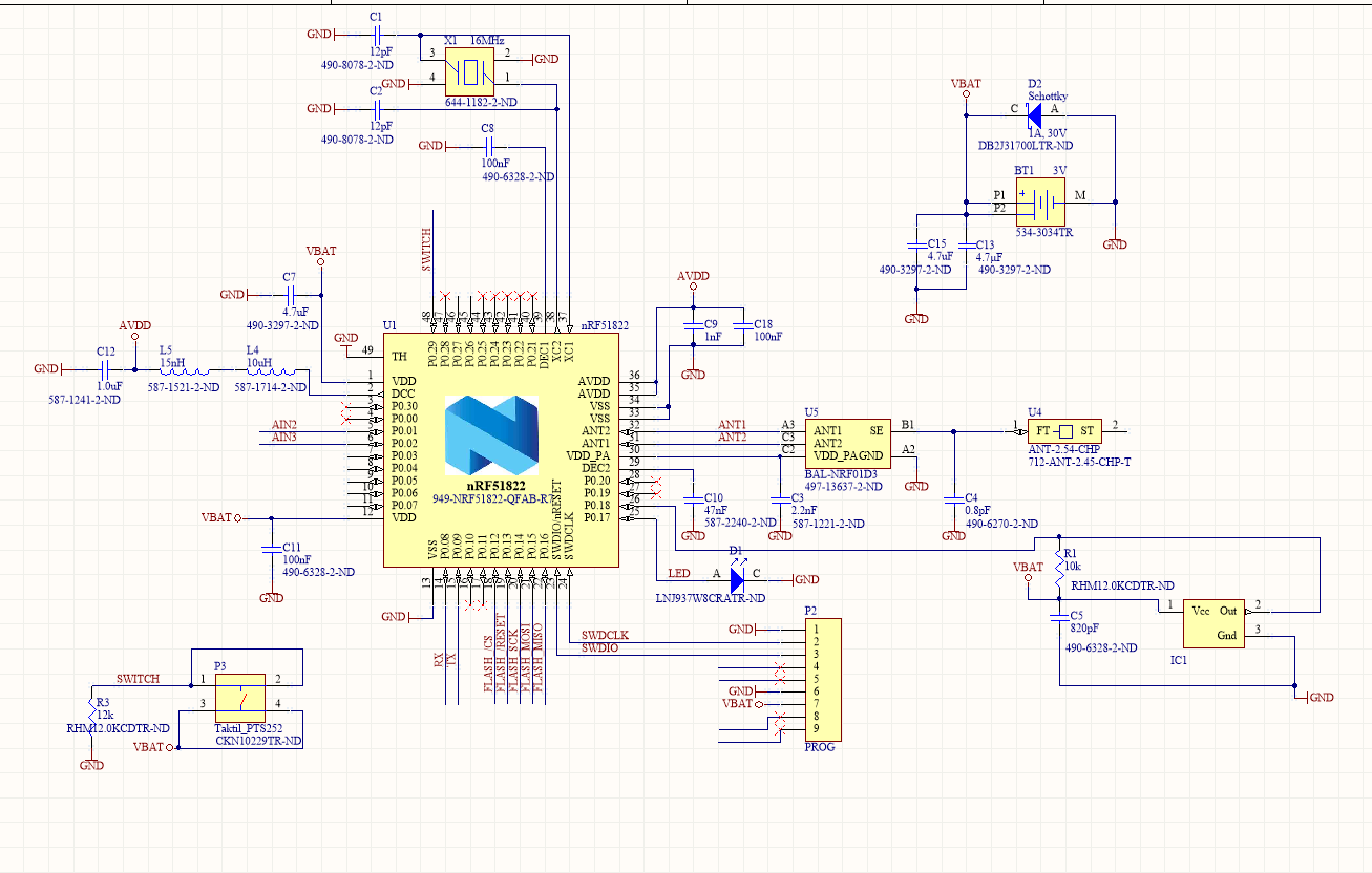
Commented that my custom PCB incorporates a 16Mhz quartz crystal and I have not put the other quartz crystal as in the design guides is optional.

If I do not connect my PCB as I can correctly program the NRF51DK KIT but when I connect my PCB to measure then it can not program my code.

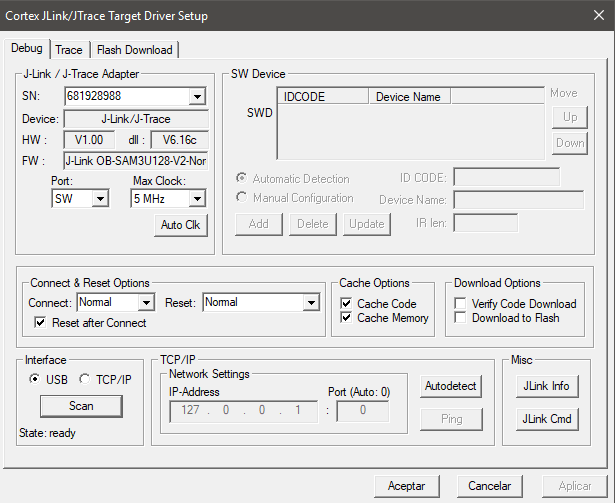
I've also tried to program it using the uVision program and the exact same thing happens. In this case the program gives me error: SW Device not found.

001.PNG

When I feed my custom PCB it stops recognizing the SW device.
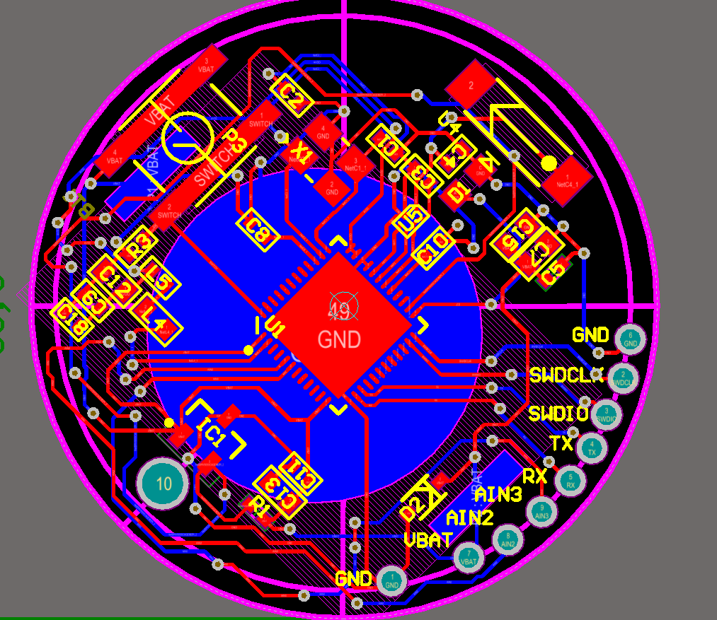
002.PNG

Routed PCB PCB.PNG

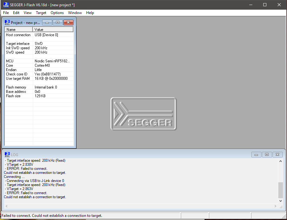
LOG J-LINK FLASH jlinkflash.PNG

  • Have you tried nRFgo Studio to program it?

    You should also double check that you didn't rotate the 16MHz xtal. It's a common mistake.

    And, double check that vbat is really there after you hook up your board. You could have onboard shorts that you haven't discovered yet.

  • Is your PCB powered by its own supply? You can not supply power through the Vteg pin. Vteg is just a voltage sensing pin and you need to power your PCB with ~2.8V to 3.3V.

    EDIT: These are your options when connecting an external device to your DK for programming:

    Options

    EDIT 2: Just a quick clarification regarding voltages. Some comments here suggests that you need more or less exactly 3.3V on your target device. The thinking being (I assume) that you need to have the same supply voltage on your target device and the Segger MCU on the DK. That is not entirely correct. The output of the 3.3V voltage regulator on the DK is actually closer to 3.2V. Then, due to the protection diodes on the DKs (shown in the schematic below) there is an additional ~0.5V voltage drop causing the entire system on the DK to be powered by ~2.8V. Hence, if your external board is powered by ~2.8V that is fine. It should also work to use a voltage on your target board a couple of 100 milliamps higher than the voltage on the DKs, but then you should use caution and use option 3 in the drawing above to avoid over voltages on the DK circuits. If you are not sure about what to do I recommend using option 2. That should be safe in most cases (unless your target device can't handle 2.8V).

    Prot

  • Good point. I forgot about that. I normally bypass vteg to the DK's VDD so I don't have to power remotely during programming.

  • My PCB is powered by a CR2032 battery and the VTEG pin transmits it to 2.85v. I have reviewed the schematic and routing of the PCB and apparently I have no short circuit and I have also checked the crystal checking that it is correct. When I do the baypass between VDD and VTEG (between the pins of the DK) when uploading the program the DK is reset and does not load the program on my custom pc.

    I keep trying ...

    I have purchased a JLINK to upload to the code, on Friday I receive it at home .... Can this be the solution?

Related