This post is older than 2 years and might not be relevant anymore
More Info: Consider searching for newer posts

HardFault with GPIOTE & SD

Hi!

I am getting a HardFault when I try to read a GATTs value inside a GPIOTE ISR handler.

I already tried setting the ISR priority to low as suggested in various posts.

Here is my code:

#include "app_settings.h"

#include "control.h"
#include "services.h"
#include "nrf_drv_gpiote.h"
#include "ble_srv_common.h"
#include "app_util_platform.h"

APP_TIMER_DEF(m_control_timer_id);

static void on_zx(nrf_drv_gpiote_pin_t pin, nrf_gpiote_polarity_t action){
    UNUSED_PARAMETER(pin);
    UNUSED_PARAMETER(action);
    //nrf_drv_gpiote_in_event_disable(ZX_PIN);

    ret_code_t err_code = 0;

    // This ISR is called when a ZX interrupt occurs
    // Start a timer in _level_ proportional ticks to allow dimming

    // Disable Triac immediately
    //nrf_drv_gpiote_out_set(TRIAC_PIN);

    // Get level value from the GATT DB
    ble_gatts_value_t gatts_value;
    gatts_value.offset = 0;
    err_code = sd_ble_gatts_value_get(m_ctl.conn_handle, m_ctl.ctl_level_handles.value_handle, &gatts_value);
    APP_ERROR_CHECK(err_code);
    float level = *((float*)gatts_value.p_value);

    // Check level boundaries
    if(level > 1){
        level = 1;
    }
    if(level < 0){
        level = 0.1;
    }
    //nrf_drv_gpiote_in_event_enable(ZX_PIN, true);

    // Calculate wait time and start timer
    // float T2 = 1.0 / 100;
    // uint32_t wait_ms = (uint32_t)(T2 * (1 - level) * 1000);
    // err_code = app_timer_start(m_control_timer_id, wait_ms, NULL);
    // APP_ERROR_CHECK(err_code);
}

// static void on_timer(void * p_context){
//     // Enable Triac
//     nrf_drv_gpiote_out_clear(TRIAC_PIN);
// }

void init_ctl(void){
    ret_code_t err_code;

    // Init GPIOTE if not yet initialized
    if(!nrf_drv_gpiote_is_init()){
        err_code = nrf_drv_gpiote_init();
        APP_ERROR_CHECK(err_code);
    }

    // Init timer for phase angle
    //err_code = app_timer_create(&m_control_timer_id, APP_TIMER_MODE_SINGLE_SHOT, on_timer);

    // Init pin for triac on
    nrf_drv_gpiote_out_config_t out_config = GPIOTE_CONFIG_OUT_SIMPLE(false);
    err_code = nrf_drv_gpiote_out_init(TRIAC_PIN, &out_config);
    APP_ERROR_CHECK(err_code);

    // Init pin for ZX ISR
    nrf_drv_gpiote_in_config_t in_config = GPIOTE_CONFIG_IN_SENSE_LOTOHI(true);
    in_config.pull = NRF_GPIO_PIN_PULLDOWN;

    err_code = nrf_drv_gpiote_in_init(ZX_PIN, &in_config, on_zx);
    APP_ERROR_CHECK(err_code);

    // Lower IRQ prio so SD does not get fucked
    NVIC_SetPriority(GPIOTE_IRQn, APP_IRQ_PRIORITY_LOW);

    // Enable ISR on ZX rising edge
    nrf_drv_gpiote_in_event_enable(ZX_PIN, true);
}

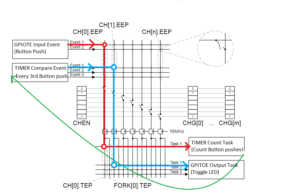
What I would like to do is having the ISR on a pin rising edge which starts a timer. The timer ISR should then set another pin to high. I am not quite sure how to make sure the priorities are set properly as apparently the priorities 0-5 are reserved for the SD. Also I do not like having to lower the priority for those said interrupts I want as they are timing critical. So using the app scheduler or the likes wont work either (as suggested in a few posts).

Thanks for any help in advance!

Best regards

Noah

    1. Are you saying that your code above with GPIOTE irq priority APP_IRQ_PRIORITY_LOW doesn't work?
    2. Assuming that you are using nRF52 then the softdevice reserves priorities 0, 1, and 4. You are free to use the other levels for application interrupts.
    3. If latency is important to you I suggest that you check out the possibility of using PPI and GPIOTE channels, together with a timer. You can make a level change on an input start the timer, and when the timer reaches a certain value it will trigger a level change on a different output pin. By using PPI you can do all this without interrupts at all and completely independent of the CPU.
    1. Yes I am saying that :) It can read the attribute during the first call (even tho the value is 0 instead of 1; yes the handles are correct, I checked that) the SD will go to the HardFault handler afterwards. (I am using SDK 14.0 and SD v5.0; maybe that's bad tho)
    2. Oh I really should have read better, thanks for the info!
    3. Ok that sounds very promising! I already have a working solution now, where I wont use the GATT DB but rather store the value myself upon write event. Maybe that solution is bad. Timing is no issue as tests have shown. But I will still try the PPI solution as it sounds great. I read about the PPI already and didn't quite understand what the purpose really is tbh. I felt like it was a messaging system but then I might have horribly mistaken. Is there a good read you can recommend, as just the bare function docs sometimes are not enough =)
  • The Programmable Peripheral Interconnect (PPI) sounds like the ideal solution to your troubles.

    Unfortunately the scarce documentation in the infocenter doesn't do the PPI any justice. It is really a powerful tool that can save you a lot of work, code lines, CPU cycles, and power. In your comment you compare it to a messaging system, which is sort of correct I suppose. You can configure one peripheral in your system to send a message on a certain event, and then that message is delivered to a different peripheral in your system which then performs some task based on that. Almost all of the nRF5 series' peripherals (SAADC, TWI, RADIO, GPIOTE, RTC, TIMER, etc. etc.) can process some sort of tasks and events and it is pretty much only your imagination that limits how you connect everything. For example:

    1. An ADC Result Done Event (SAADC->EVENT_RESULTDONE) can trigger a timer Count Task (TIMERx->TASK_COUNT). This way you can sample a signal e.g. 100 times while the CPU is sleeping, but have the timer count the number of samples performed and wake the CPU up to process the samples at the 100th sample.
    2. An input GPIO pin pulled high to low (GPIOTE->EVENT_IN can start one or more TWI transfer tasks (TWIM->TASKS_STARTTX). This is ideal for reading data from a sensor with a Data Ready signal.
    3. In some (rare) cases it is also useful to use the PPI to "loop" events in a peripheral back into the same peripheral and make it perform a task.

    Below I have pasted some basic code that counts the number of times an input signal is pulled high to low (by using BUTTON 3 on the nRF5 DK). The push of the button triggers a GPIOTE event which is counted by TIMER 1. When the counter register in TIMER 1 matches the value in the Capture Compare register #0 (which in this case is 3) the timer generates an event which is routed back to the GPIOTE module which responds by toggling a GPIO pin.

    #include <stdbool.h>
    #include <stdint.h>
    
    #include "app_util_platform.h"
    #include "boards.h"
    
    void TIMER1_IRQHandler(void)
    {
        NRF_TIMER1->EVENTS_COMPARE[0] = 0;
        nrf_gpio_pin_toggle(LED_2);
        int i = 0;
        while(i<0xFFFFF)
    	{
    		i++;     
    	}
    }
    
    void ppi_setup(void)
    {
    	/***************
    	 * GPIOTE Setup
    	 **************/
    	// Input GPIOTE event triggered on the push of button 3 on dev kit
    	nrf_gpio_cfg_input(BUTTON_3, NRF_GPIO_PIN_PULLUP); // Enable pullup on the GPIO
    	NRF_GPIOTE->CONFIG[0] = (GPIOTE_CONFIG_MODE_Event << GPIOTE_CONFIG_MODE_Pos) | 
    						(GPIOTE_CONFIG_POLARITY_LoToHi << GPIOTE_CONFIG_POLARITY_Pos) | 
    						(BUTTON_3 << GPIOTE_CONFIG_PSEL_Pos);
    
        // Output GPIOTE task (Toggle a GPIO). 
        NRF_GPIOTE->CONFIG[1] = (GPIOTE_CONFIG_MODE_Task << GPIOTE_CONFIG_MODE_Pos) | 
                                (GPIOTE_CONFIG_POLARITY_Toggle << GPIOTE_CONFIG_POLARITY_Pos) | 
                                (GPIOTE_CONFIG_OUTINIT_High << GPIOTE_CONFIG_OUTINIT_Pos) | 
                                (LED_1 << GPIOTE_CONFIG_PSEL_Pos);
    
    
        /***************
         * COUNTER Setup
         **************/
        // Clear and disable interrupts before configuring new interrupts
        NVIC_DisableIRQ(TIMER1_IRQn);
        NVIC_ClearPendingIRQ(TIMER1_IRQn);
        /* Conigureing TIMER
         * Set mode to low power counter mode to save power
         * Use 32 bit counter mode. Doesn't really matter in this example
         * Enable shortcut to clear the Capture Compare register #0 on compare event
         * Set capture compare register #0 to 3 to generate events and interrupts on every third GPIOTE input events
         * Enable Timer capture compare interrupt 
         */
        NRF_TIMER1->MODE = TIMER_MODE_MODE_LowPowerCounter << TIMER_MODE_MODE_Pos;
        NRF_TIMER1->BITMODE = TIMER_BITMODE_BITMODE_32Bit << TIMER_BITMODE_BITMODE_Pos;
        NRF_TIMER1->SHORTS = TIMER_SHORTS_COMPARE0_CLEAR_Enabled << TIMER_SHORTS_COMPARE0_CLEAR_Pos;
        NRF_TIMER1->CC[0] = 3;
        NRF_TIMER1->INTENSET = TIMER_INTENSET_COMPARE0_Enabled << TIMER_INTENSET_COMPARE0_Pos;
        NRF_TIMER1->TASKS_START = 1;
    
        NVIC_SetPriority(TIMER1_IRQn, _PRIO_APP_LOWEST);
        NVIC_EnableIRQ(TIMER1_IRQn);
    
    
        /***************
         * PPI Setup
         **************/
         // Connect the Timer Count task with the GPIOTE input event (To count button pushes)
        NRF_PPI->CH[0].TEP = (uint32_t)&NRF_TIMER1->TASKS_COUNT;
        NRF_PPI->CH[0].EEP = (uint32_t)&NRF_GPIOTE->EVENTS_IN[0];
        NRF_PPI->CHEN |= PPI_CHEN_CH0_Enabled << PPI_CHEN_CH0_Pos;
    
        // Connect the timer Capture compare event to the GPIOTE Out Task (to toggle the LED on every third button push)
        NRF_PPI->CH[1].TEP = (uint32_t)&NRF_GPIOTE->TASKS_OUT[1];
        NRF_PPI->CH[1].EEP = (uint32_t)&NRF_TIMER1->EVENTS_COMPARE[0];
        NRF_PPI->CHEN |= PPI_CHEN_CH1_Enabled << PPI_CHEN_CH1_Pos;
    }
    
    
    /**@brief Function for application main entry.
     */
    int main(void)
    {
        NRF_POWER->DCDCEN = 1;
        nrf_gpio_cfg_output(LED_2);
        ppi_setup();
    
        // Enter main loop.
        for (;;)
        {
            // Do nothing but sleep
          __WFE();
          __SEV();
          __WFE();
        }
    }
    

    Below you can see how this code connects the tasks and events to the PPI channels: adlfjk

    Below you can see a plot of the power consumption. You can see that most of the time the system uses little to no power. When the button is pressed the pull up resistor (~13kOhm) causes a small current of ~200uA. Every third push of the button an interrupt is triggered and the CPU is started. The result is shown as the 4mA spikes.

    image description

  • Since I couldn't find any good examples or documentation anywhere, I took the opportunity to write a bit about the PPI in an answer below (it got long). Hopefully it will be useful to others too.

    Since you have found a working solution, can we consider the matter as solved? SD 5 is the one you are supposed to use with SDK 14 so I don't think that is an issue.

  • Wow you are great and very generous with your time sir! Thank you so much! I will try this out as soon as I have some more urgent matters resolved as the software solution works just fine for the time being. I will then provide you with some more feedback too, sorry for the late and scarce answer ... Best, Noah

Related