This post is older than 2 years and might not be relevant anymore
More Info: Consider searching for newer posts
This discussion has been locked.
You can no longer post new replies to this discussion. If you have a question you can start a new discussion

Can’t program BT832 Module using NRF52-DK

I have read articles on the forum, watch youtube but still no luck. Actually I failed to find step by step tutorial how to do it from start to the end. Most of them touch wiring stuff only.

Hardware:

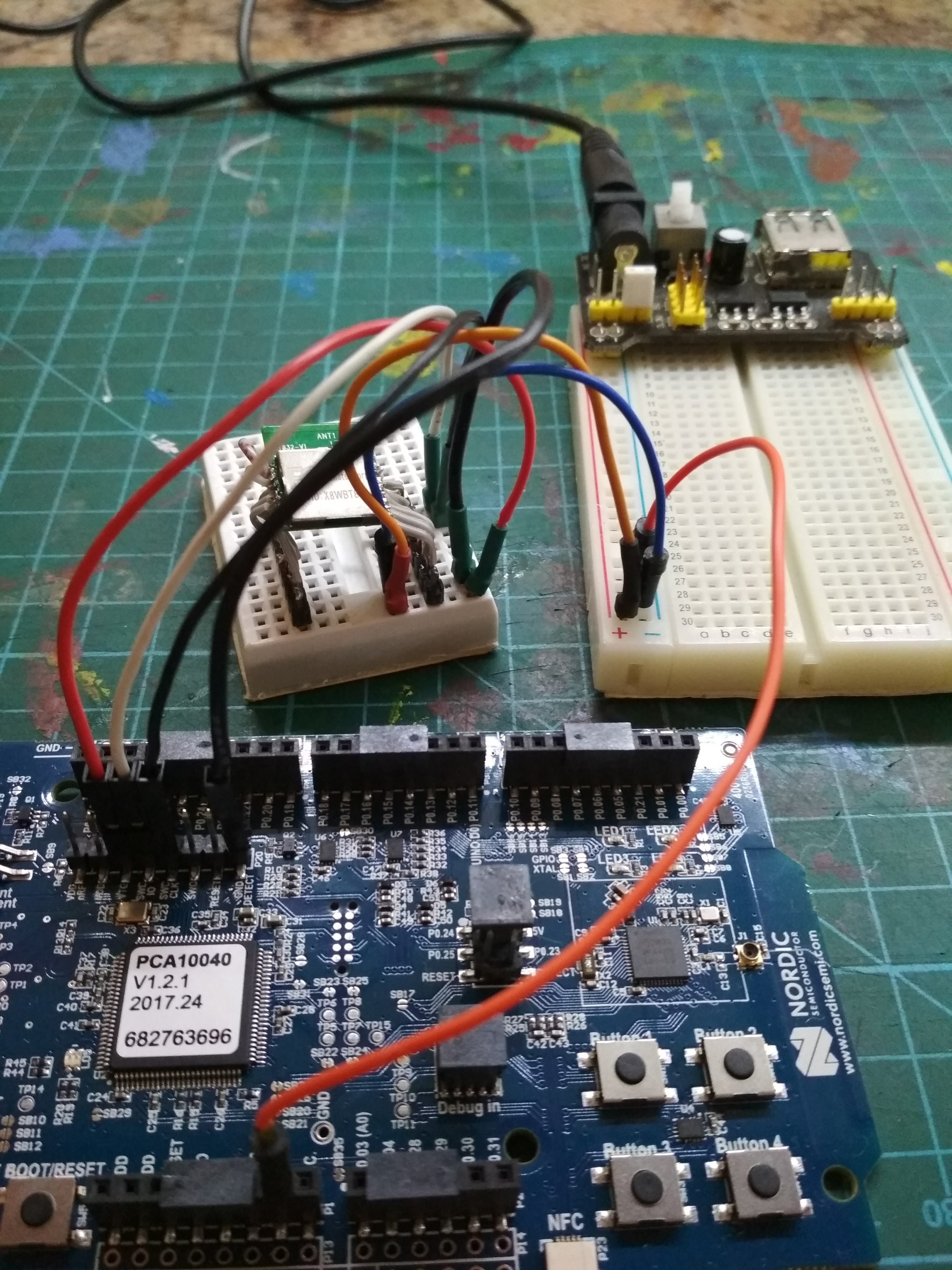
Wire thing up, just like devzone.nordicsemi.com/.../ or devzone.nordicsemi.com/.../ (tried both, with external 3.3v power for the BT832 module and w/o)

image description

Try to flash:

Using any ble peripheral example from SDK:

  • Cd pca10040/s132/armgcc
  • Make, make flash_softdevice, make flash
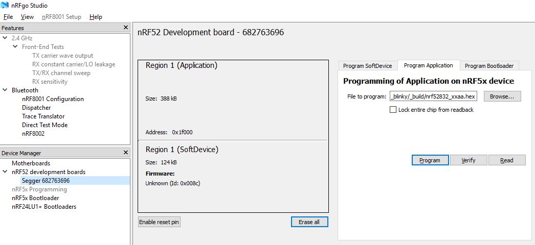
Using NRFog Studio:

  • See only 2 regions. No matter power I BT832 externally or no.
  • Re-flash both softdevice and application with appropriate binaries.

image description

Both actions successfully flash NRF52-DK only, but the BT832 left blank. How I check - I try to discover BLE devices using phone (nRF Connect application). NRF52-DK - fine, but BT832 invisible.

What am I doing wrong? Wiring schema I found in many places and it seems fine. Maybe I should programm is some other way and specify some extra attributes to point external device, not just NRF52-DK?

  • Hi Alexey,

    You said you have found only guides how to wire the thing and that you read them but from what I see on your photo you don't wire P20 header properly! Internal SEGGER J-Link FW needs to detect that there is external target on that port otherwise it obviously flashes internal nRF5x chip on the DK. So please kindly power your target module from first 3V3 (VDD nRF) PIN on P20 header (this can go alternatively from different 3V3 PIN on nRF5x DK or even from external source - if you then ground the system properly!) and short second and third PINs (VDD and VTG) so that SEGGER J-Link can detect your intentions.

    Also your wires might be too long, uneven in the length and too clumpsy (= vulnerable to noise). JTAG/SWD flashing is surprisingly sensitive to the wiring, using short (as short as possible) and thick cables can save you from few days of debugging (= searching for ghost in the system). But this is just secondary advice "in case you still face the troubles", the first one might already solve your problem.

    Cheers Jan

  • Which app did you flash into the BT832? The BLE peripheral beacon app?

  • I have tried the way you propose, power BT832.VDD with P20.VDDnrF connect P20.VDD and P20.VTG with BT832.VDD. In this way all 4 pins are shorted. photos.app.goo.gl/Eq9UYfXMcQdySuYo2 photos.app.goo.gl/kDpoiK8pomsBtxzj1

    Each time I try to connect to NRF52-DK via nRFgo Studio, the board goes to reboot. Try to flash from console gives: photos.app.goo.gl/e3gR4iEb3Q9XQAj43

    Do you think this is wires length issue?

  • Initially I have tried on experimental_ble_app_blinky, but then on many one, e.g. ble_app_gls. Tried beacon also. Should I get any issues with beacon?

  • I suggested the beacon app as the nRF Connect should see the advertising if the the BT832 is working.

    I have not used BT832 before but I did load the BC832 eval board using the PCA10040 for my BLE work. Assuming BT832 is not that different from BC832 the wiring connections should be

    P20 BC832

    GND DETECT --> GND; VTG --> VDD; VDD --> VDD; SWDIO --> SWDIO; SWDCLK --> SWCLK;

    Can you verify again you have the above wiring set up correctly between your PCA10040 P20 header and the BT832 module?

Related