
How do you do 1.In the Nordic \ nRF5_SDK_12 _f012efa 2.0-3 d \ examples \ peripheral here, there are three PWM routines: Low_power_pwm, pwm_driver, pwm_library but only low_power_pwm and pwm_library can be used for NRF51822 right?
2.Low_power_pwm pwm_library and what is the difference between the two routines?Use under what circumstances?
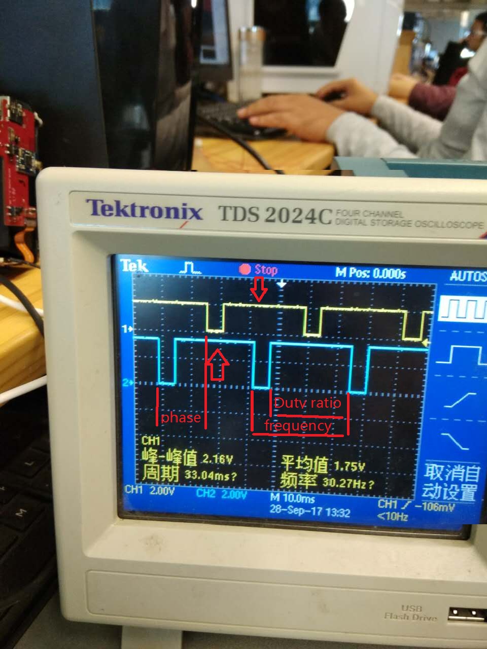
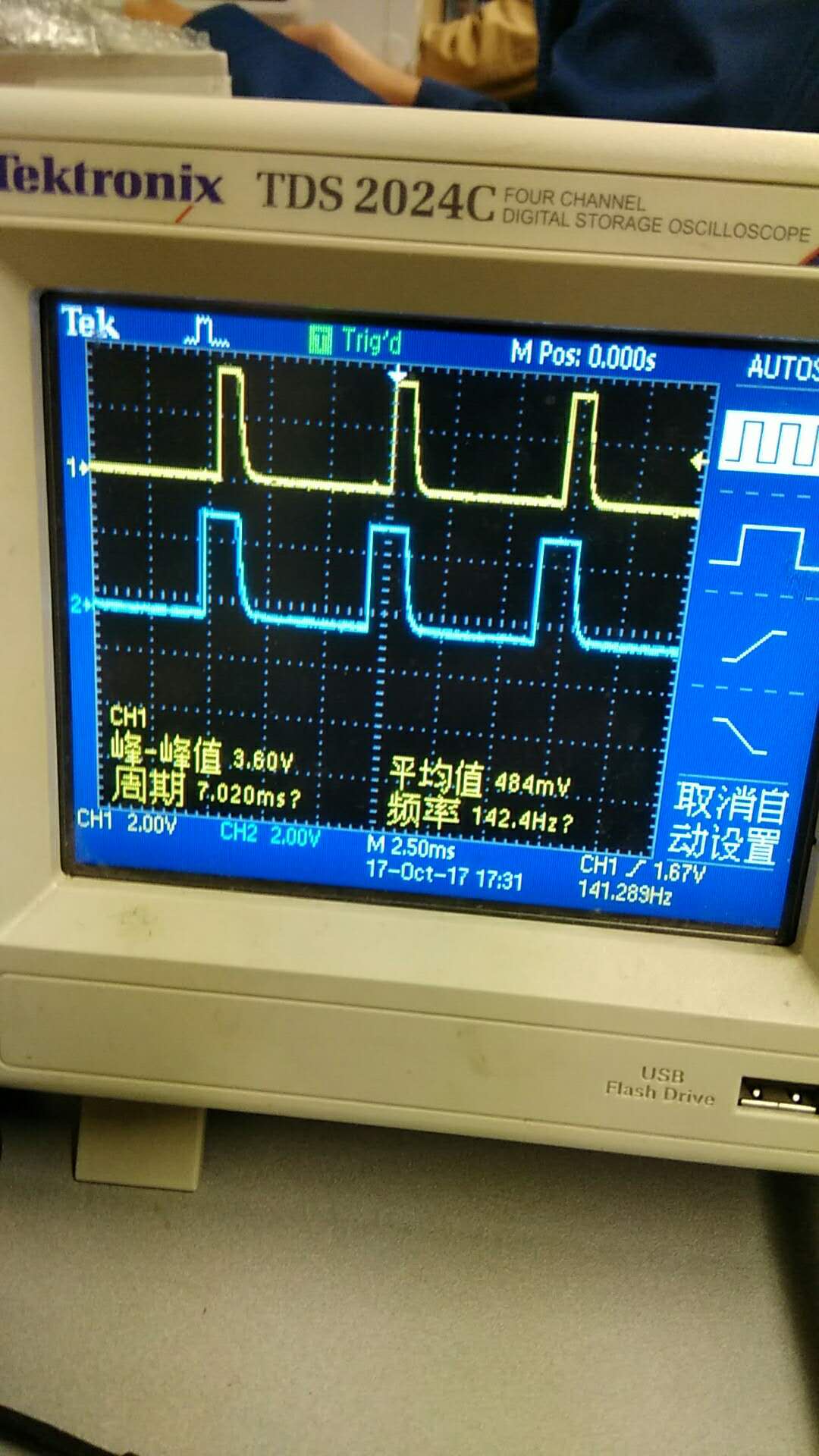
3.NRF51822 should I use to produce two lines of PWM waveform, and the need to control the frequency and duty ratio, two road PWM phase, which routines for use?As shown in figure
4.Using pwm_library this routine I set like this: app_pwm_config_t pwm1_cfg = APP_PWM_DEFAULT_CONFIG_2CH(5000L, 3, 4); /* Switch the polarity of the second channel. */ pwm1_cfg.pin_polarity[1] = APP_PWM_POLARITY_ACTIVE_HIGH;
/* Initialize and enable PWM. */
err_code = app_pwm_init(&PWM1,&pwm1_cfg,pwm_ready_callback);
APP_ERROR_CHECK(err_code);
app_pwm_enable(&PWM1);

	  app_pwm_config_t pwm2_cfg = APP_PWM_DEFAULT_CONFIG_2CH(5000L, 1, 2);
/* Switch the polarity of the second channel. */
pwm2_cfg.pin_polarity[1] = APP_PWM_POLARITY_ACTIVE_HIGH;

/* Initialize and enable PWM. */
err_code = app_pwm_init(&PWM2,&pwm2_cfg,pwm_ready_callback);
APP_ERROR_CHECK(err_code);
app_pwm_enable(&PWM1);
  APP_ERROR_CHECK(app_pwm_channel_duty_set(&PWM1, 0, 50));
  APP_ERROR_CHECK(app_pwm_channel_duty_set(&PWM2, 0, 50));
Duty ratio is 50%, but it isn't ,How do you set this and phase?
5.If you use low_power_pwm this routine, phase how Settings?
uint32_t err_code; low_power_pwm_config_t low_power_pwm_config;
APP_TIMER_DEF(lpp_timer_0);
low_power_pwm_config.active_high    = false;
low_power_pwm_config.period         = 220;
low_power_pwm_config.bit_mask       = BSP_LED_0_MASK;
low_power_pwm_config.p_timer_id     = &lpp_timer_0;
low_power_pwm_config.p_port         = NRF_GPIO;

err_code = low_power_pwm_init((&low_power_pwm_0), &low_power_pwm_config, pwm_handler);
APP_ERROR_CHECK(err_code);
err_code = low_power_pwm_duty_set(&low_power_pwm_0, 20);
APP_ERROR_CHECK(err_code);

APP_TIMER_DEF(lpp_timer_1);
low_power_pwm_config.active_high    = false;
low_power_pwm_config.period         = 200;
low_power_pwm_config.bit_mask       = BSP_LED_1_MASK;
low_power_pwm_config.p_timer_id     = &lpp_timer_1;
low_power_pwm_config.p_port         = NRF_GPIO;

err_code = low_power_pwm_init((&low_power_pwm_1), &low_power_pwm_config, pwm_handler);
APP_ERROR_CHECK(err_code);
err_code = low_power_pwm_duty_set(&low_power_pwm_1, 150);
APP_ERROR_CHECK(err_code);
Thank you very much looking forward to your reply.
