This post is older than 2 years and might not be relevant anymore
More Info: Consider searching for newer posts
This discussion has been locked.
You can no longer post new replies to this discussion. If you have a question you can start a new discussion

Shall i use Doubler circuit using MCP1640 with single AA battery power supply for nRF52832?

Hello Sir,

I have developed small and compact product using nRF52832 Soc. Due to size limitation and device is portable. I have attached snap shot of power supply circuit as per this circuit this switch is use only for ON device and after some period device will completely shut down not in sleep mode it achieve by MCP1640 EN pin = 0.

This doubler IC EN pin is control in nordic program by define on GPIO pin when momentary switch press EN high and nRF52832 chip ON and then quickly logic high is provide to MCP1640 EN pin in program. After some specified period it will automatically go to shut down by EN= GND. This logic we are using for power save to improve battery life. For controlling enable pin i am using n Channel Power MOSFET with very low VGSth.image description 
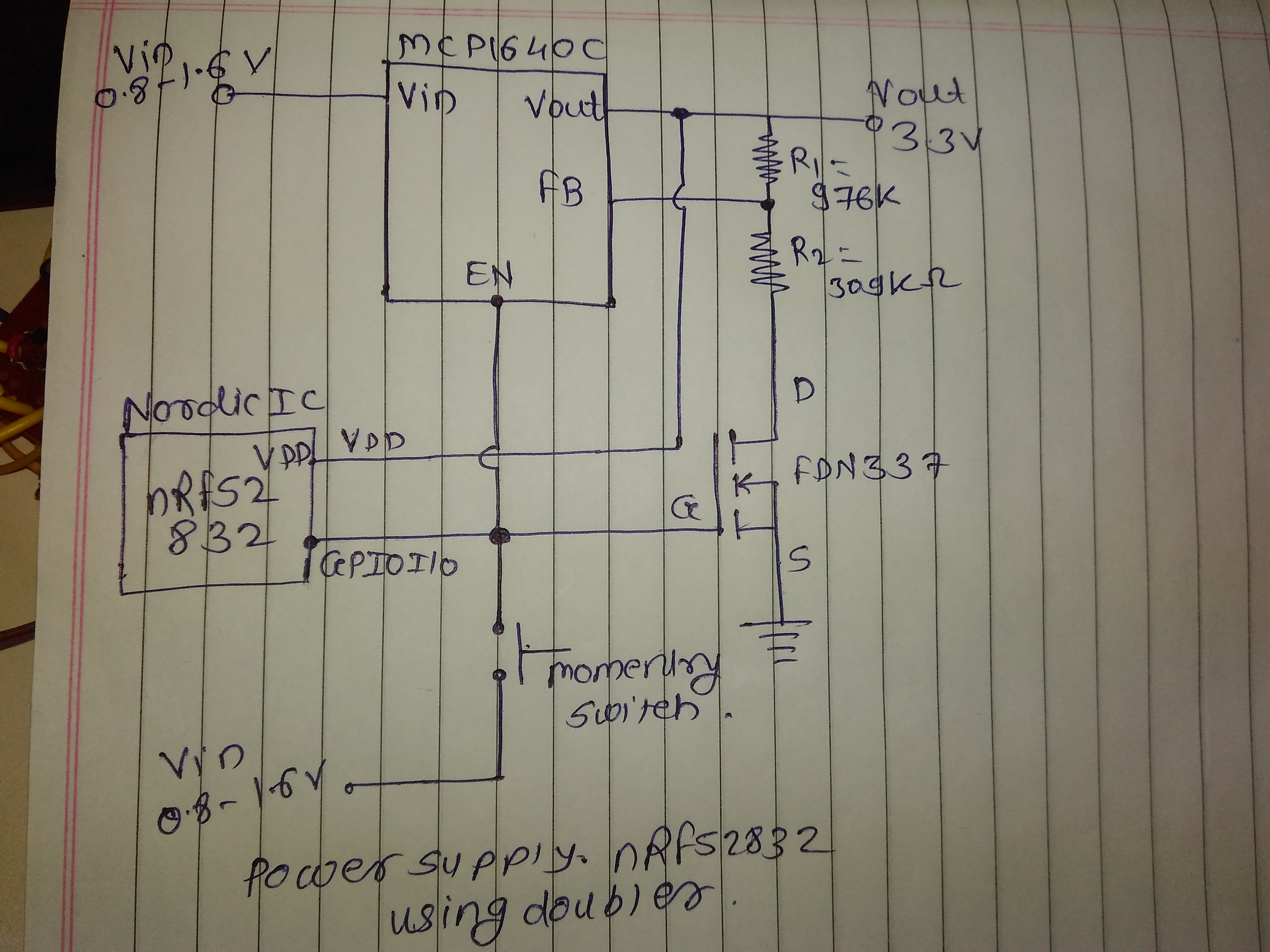
So sir please give me suggestion can i use this type of power source.

  • Hi,

    1. Why do you need the MOSFET? To stop current flowing through the resistor divider when the MCP1640 is off? The datasheet claims that there is a "true" load disconnect when the device is disabled so I can't see why this would be a problem.
    2. When you push the momentary switch the voltage on the GPIO will be 0.8-1.6V (Vin). Then, when the MCP1640 has started, it will supply the nRF52's VDD with 3.3V (Vout). When the nRF52 has started it will set the GPIO to high, in other words 3.3V (Vdd). This will probably all happen before the user has managed to release the switch and at a brief moment in time (probably a few 100s of milliseconds) the nRF52 will try to set the GPIO to Vdd while the switch forces it to Vin. This can damage the nRF52, but a resistor between the switch and the GPIO would probably make it a little safer.
  • MOSFET is use because when i shut down MCP1640 in nordic program mean GPIO GND = EN pin at that time vout of MCP1640 volatge is slowly decrease at the same time nRF52832 again ON because it operate upto 1.7V. Thats why for avoid again ON nordic we are using MOSFET, Can you suggest me alternate solution for the same. How to stop current flowing the resistor divider when the MCP1640 is off? For safer nRF52832 chip which value resistor i use between the switch and the GPIO. If i add resistor nordic chip is safe should i use in my final design. If i add resistor is it increase any extra current consumption or not.

    Thanks.........

  • Are you saying that the nRF52 is restarting after you have disabled the MCP? Shouldn't you have a clean discharge curve on Vout after you disable the MCP?

  • Ya write, nRF52 is restart and it is ON upto specific time define in program after that it again restart. If i use MOSFET i will shut down completely and when i press momentary switch it will ON. Can you suggest me resistor value.

    Thanks..

  • The resistor value needs to be large enough to limit the current drawn from the GPIO and protect the GPIO protection diodes inside the SoC. A value between 1k-10k should be fine. If you add the resistor the system will not draw more current. If anything, it will reduce the current since you won't get the short circuit between Vdd and Vin.

Related