This post is older than 2 years and might not be relevant anymore
More Info: Consider searching for newer posts
This discussion has been locked.
You can no longer post new replies to this discussion. If you have a question you can start a new discussion

nRF52840 UART connection

Hi support team,

I'm using Nordic nRF52840 with PCA10056 and SDK 14.1. I have a problem with UART connection. I have a custom board which need to hook up UART connection with Nordic PDK for data or command transferring. And also I need annother UART connection between Nordic PDK and PC, which is used to print debug trace. I can download firmware to the PDK and also print messages to the virtual COM port via USB.

  1. I know nRF52840 has two instances of UART. Is the virtual COM port(USB interface to PDK MCU) one of UART instance? If not, what is the difference?

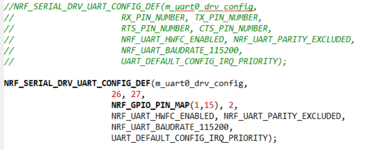
  2. I started with the example "nRF5_SDK_14.1.0_1dda907\examples\peripheral\serial", I can see UART data from the USB interface of the PDK MCU by Tera Term. Then I tried to change UART pins to my custom ones. I used an FTDI usb to uart convertor to hook up my PC with PDK on gpio pins of P0.26(RXD), P0.27(TXD), P0.02(CTS), P1.15(RTS). Also I change the UART config in the example code like this:

image description

However, I can't see any UART output from the my FTDI USB port or the PDK USB interface port. I'm pretty sure that my FTDI connection is good. Could someone help about this?

3.Still started with the example "examples\peripheral\serial", if I retain the USB interface for PDK UART connection, how should I do if I want another UART connection between my custom board and PDK?

Thank you in advance.

Best regards,

Tengfei.

  • I'm having the same issue it seems changing the uart pins from the default ones causes a hard fault for some reason. Really annoying if you ask me.

  • Hi,

    On the nRF52840-PDK you have 2 USB connectors. The first one is connected to the on-board Segger J-Link debugger/programmer. In the documentation, this MCU is referred to as the “Interface MCU”. See this page at infocenter. The interface MCU features a USB to UART Bridge (virtual COM port). While you can choose any free GPIO pins you want for a regular UART connection on the PDK, the UART connection between the interface MCU and the nRF52840 is fixed, and given in Table 1 here:

    image description

    The other USB interface(nRF USB) is connected directly to the USB pins on the nRF52840. The signal/USB pins consist of the D+ and D- pins. They are dedicated pins, and not available as standard GPIOs. The USBD peripheral can act as a virtual COM port using the nRF USB connector. This is shown in the USB CDC ACM example in the SDK. In this case, we are not using any UART instance.

    2 ) Does the "FTDI usb to uart convertor" use flow-control and Parity excluded ? Do you have a logic analyzer(e.g. Saleae) so you can use to see what is happening on the wires ?

    3 ) Then you need to create a new serial uart instance. This is done by using the macro NRF_SERIAL_UART_DEF().

    NRF_SERIAL_UART_DEF(serial_uart0, 0); // Create instance of a serial uart  using UARTE0
    NRF_SERIAL_UART_DEF(serial_uart1, 1); // Create instance of a serial uart  using UARTE1
    
    ret = nrf_serial_init(&serial_uart0, &m_uart0_drv_config, &serial_config0);
    APP_ERROR_CHECK(ret);
    
    ret = nrf_serial_init(&serial_uart1, &m_uart1_drv_config, &serial_config1);
    APP_ERROR_CHECK(ret);
    
  • Thank you, Sigurd. I have figured out where I was wrong. The right way of UART connection should be "RX-TX, TX-RX, CTS-RTS, RTS-CTS", just to remind others who might get into the same trouble like me. link to my question this link of my another question will be useful for the UART related problems.

Related