This post is older than 2 years and might not be relevant anymore
More Info: Consider searching for newer posts

PCB Antenna. Tuning not necesary

Hello,

I am designing a board based on the SoC nRF51822. Since this is a homemade project I do not have lab equipment so I can not measure antenna impedance and therefore tune it. I found this design note from Texas Instruments:

www.ti.com/.../swru120b.pdf

They claim its impedance it's 50 ohm so external components are no required. I am wondering if I can just attach output pin from balun to input pin of the antenna.

This is my layout and shematic

image description

image description

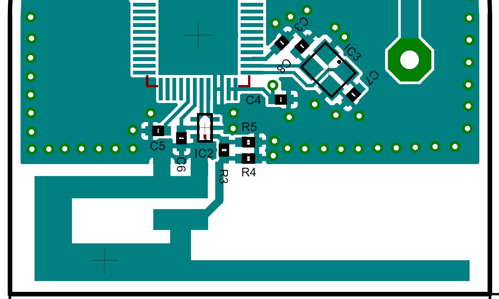
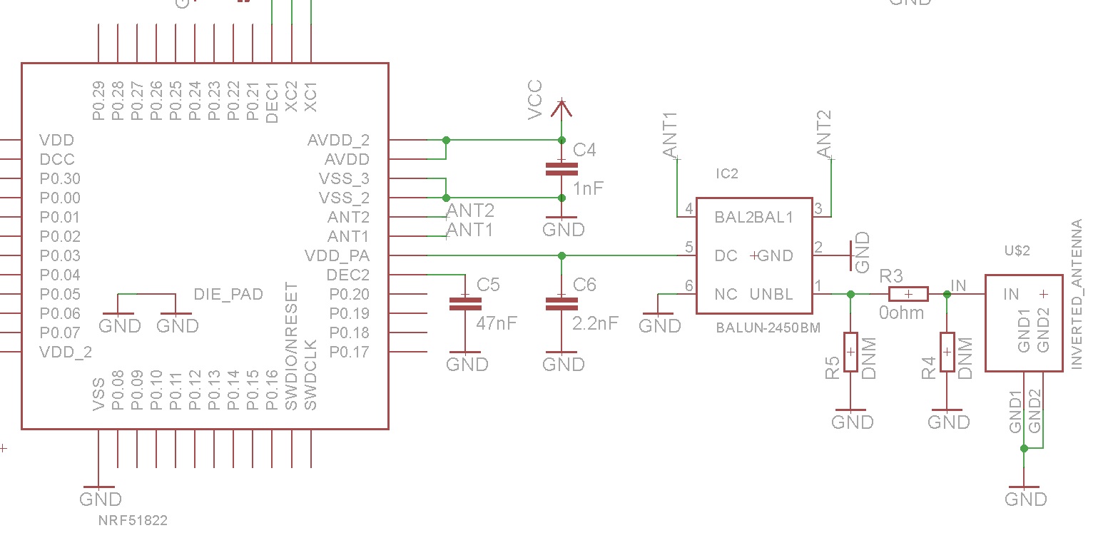
I added a pi-network just in case, but initially I will not mount R5 and R4. R3 will be a 0 ohm resistor.

Thank you.

  • Yes, you can connect the output of the balun to the input of the antenna. You have added pi-network, but unless you are doing measurements on the antenna, just use a 0 Ohm in R3. You might have a little bit more loss than in an optimized situation, but you should still see some good range even with an antenna that haven't been optimized.

    As you suspect, the antenna characteristics will change slightly based on size and shape of ground plane, distance to other metal parts, housing, where it's worn/used and so on. So the antenna might be tuned for a good 50 Ohm characteristics on the TI test board, but for all other application it will be slightly different. But the difference is usually not noticeable in a normal range/use case.

  • I thik I'm going to remove the pi-network. Even if it gives the chance to tune the antenna, I actually can't do it without lab equipment. Maybe by measuring RSSI? Sounds messy. As you suggest, it should work more or less fine. I don't need low range communication (with a couple of meters it's okay). Thank you!

Related