
I'm trying to programmate a simple blinkind led project to a custom board with a nRF51822 I did. I'm using a stm32 discovery to connect the custom board throw the SWD port. I'm working with Keil uVision5. Right know, keil see the st-link module of the stm32 board, and also my microprocessor nRF51822. The program compiles without any kind of errors and I can load the programm to the custom board with no problems, also I can use the debugging and go throw the code step by step. No problems. But, I'm not seeing any result in the board. I can't see the led blinking. And I don't know why. I had read the hole topics about this in this forum, I had search in Internet and tryed different variotions of the code... without result. A couple of thing more that you hould know 1- I made the board by myself. Hand solding. 2- The memory Areas I'm using IROM1: 0x0, 0x40000, IRAM1: 0x20000000, 0x4000 3- I have check the led polarity hundred of times. I also changed the led, and tested the new led before solding it.
What I have in mine: 1- May be the clocks are not wornikg right? How can I check that or try to use the internal clock instead? 2- May be the problems are in the board itself. I have check with a good microscope the contacts, but some places is dificult to check beacuse of the components. I have real doubt about the pin of the led. I haven't check the real voltage during the program's work. Anyway, right know I don't have the instruments to do this.
The program is a edit project of the blinky example. I had tried the softdevice version, and the one without it with the same result. The code I'm using is:
/* Copyright (c) 2014 Nordic Semiconductor. All Rights Reserved.
 *
 * The information contained herein is property of Nordic Semiconductor ASA.
 * Terms and conditions of usage are described in detail in NORDIC
 * SEMICONDUCTOR STANDARD SOFTWARE LICENSE AGREEMENT.
 *
 * Licensees are granted free, non-transferable use of the information. NO
 * WARRANTY of ANY KIND is provided. This heading must NOT be removed from
 * the file.
 *
 */

/** @file
 *
 * @defgroup blinky_example_main main.c
 * @{
 * @ingroup blinky_example
 * @brief Blinky Example Application main file.
 *
 */

#include <stdbool.h>
#include <stdint.h>
#include "nrf_delay.h"
#include "nrf_gpio.h"
#include "boards.h"

//const uint8_t leds_list[LEDS_NUMBER] = LEDS_LIST;

/**
 * @brief Function for application main entry.
 */
int main(void)
{
    // Configure LED-pins as outputs.
    nrf_gpio_cfg_output(25);

    // Toggle LEDs.
    while (true)
    {
				nrf_gpio_pin_clear(25);

				nrf_delay_ms(1000);

				nrf_gpio_pin_set(25);

				nrf_delay_ms(1000);

    }
}


/** @} */
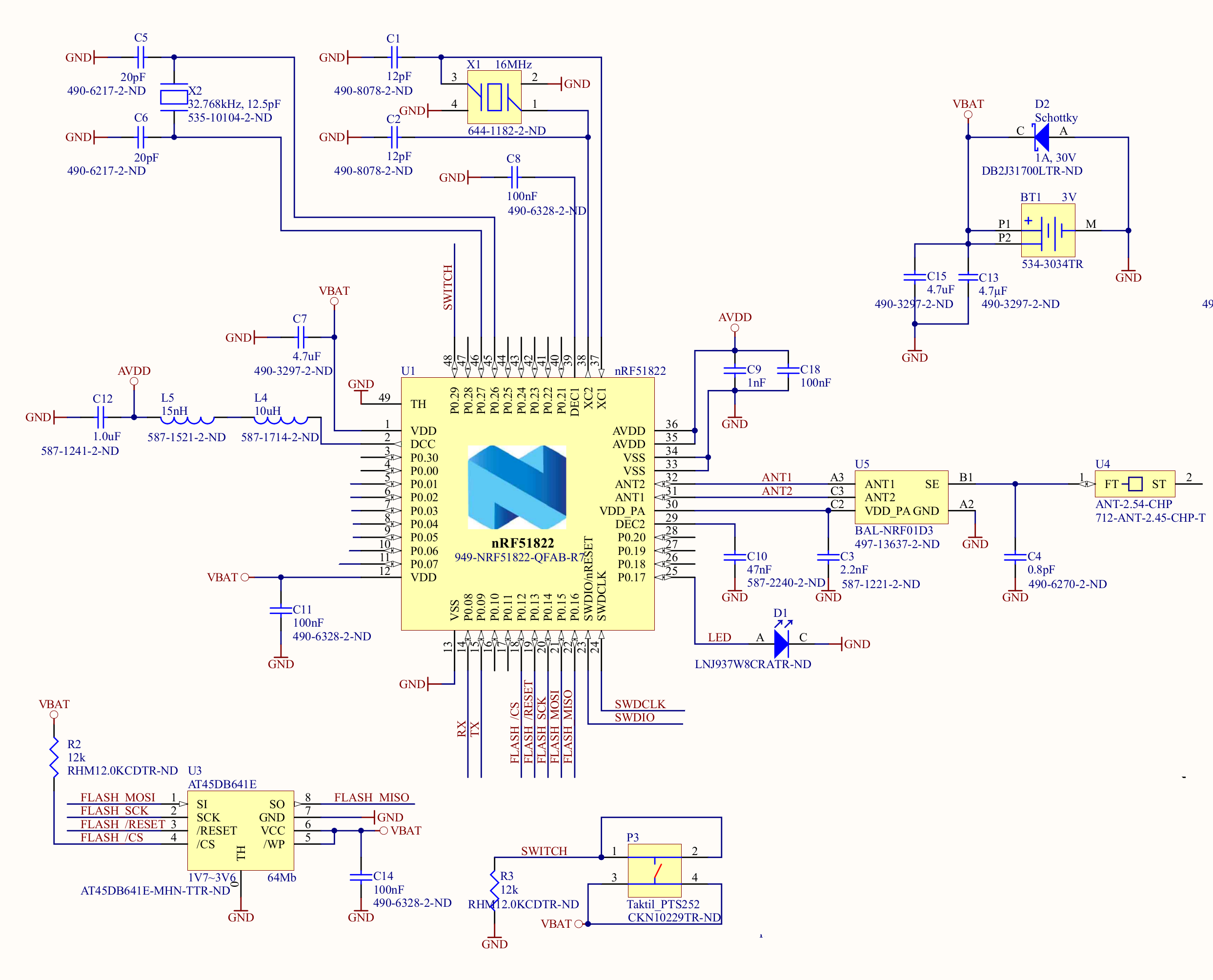
So, I'm just trying to blink the only led of the board (pin P0.17, so the number 25) . You can see the details in the schematics picture in the end of the post.
The schematics of the board based on a openbeacon.org project. So the board design it's ok. Here are the details:
Thank you for your help. I'm really stack with this, even in dreams trying to resolve the problem.

