Edit: Added schematics and information on how the value should be found.
In nRF52 a balun is integrated into the chip, so there is only one ANT pin. Because of this integrating an antenna is much easier. Now only a matching network inserted between the ANT pin and your antenna is needed.
An example of this matching network can be found on our infocenter page, under
nRF52 Series -> nRF52832 -> Reference circuitry (link). A reference design can be downloaded from here.
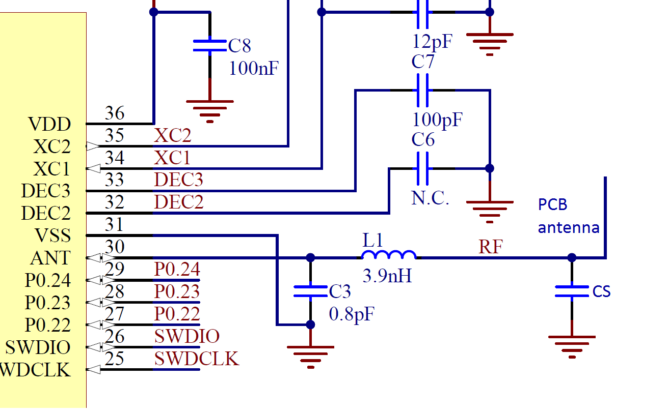
Figure 1 at the infocenter page show how the antenna can be matched with two components (C3 and L1) to a 50 ohm antenna. Please note that if you use this is it very important that the layout from the reference design is used, since the lines between the components is a part of the matching network.
The antenna can be a quarter wave monopole antenna. A whitepaper describing how such an antenna can be designed and matched to 50 ohm can be found here. This paper is written for nRF51 so the section describing how the antenna should be connected to the chip is not accurate. With nRF52 only a shunt component between the matching network and the antenna is needed. The picture below show how this can be achieved, where CS is a shunt capacitor. The value of CS need to be found by tuning, using a network analyzer. This is because the impedance of the antenna will vary due to the surrounding (casing, pcb layout etc). In the nRF52 DK the value of this capacitor is 1.2pF which can serve as a starting point. More information on how (and why) the antenna can be tuned can be found in this whitepaper.
I would also recommend you to look at how this is done in the nRF52 DK. Schematics and layout files can be downloaded from here (download tab: "nRF52 DK Hardware Files").
Hi. This is and the whitepaper is very helpful. In the reference design files inductor L1 and capacitor C3 are laid out, but the antenna trace is only 1.873mm long and there is no shunt capacitor CS. I am thinking of designing a board incorporating the reference design. I have access to a network analyser and some buddies who can help me use it to find the right value for CS, but am unsure of how long to make the PCB antenna in the first place. Is there any guidance you can offer? If I get it wildly wrong, I may not be able to find a good match.