BobLouwe.logicdataHi devs,
I'm setting up my own .NET mircro framework stack for the Adafruit nRF8001 Break Out board. When write the Reset port I do get an interrupt on the Ready port, but when I start reading from the SPI I getting all 0xFF. When I send a Test command (0x02, 0x01, 0x02) and put the REQN low (or REQ high) I do get the interrupt on the Ready port, but reading from the SPI gives me all 0x00.
I assume my SPI is not configured correctly, but I've read the documentation and it seems to be correct.
Thanks.
EDIT:
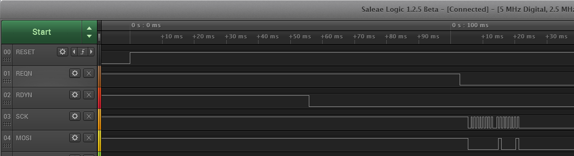
Capture file