This post is older than 2 years and might not be relevant anymore
More Info: Consider searching for newer posts

QDEC SAMPLEPER Register'Problem

Checking QDEC (Quadrature decoder) of nRF52832.

But, In a SAMPLEPER Register(0x508) when set to 128us(0) or 256us(1) does not occur SAMPLERDY Event.

On the other hand, Setting from 512us(2) to 131ms(10) and SAMPLERDY Event has occurred without problems.

Please explain what the problem is.

※ Note(Using the Example of qdec code.)

※ SAMPLERDY Event is Number3

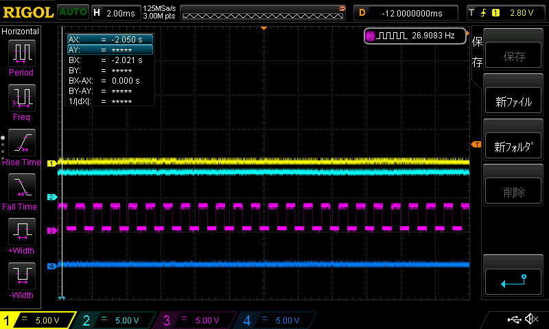
  1. Wave Capture file for 128us / 256us image description

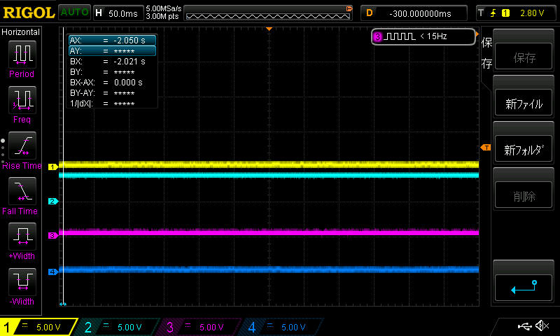
  2. Wave Capture file for 512us image description

  • Hi,

    There is an error with the example when using it below 1024 µs, I will forward this information.

    Meanwhile you can use this code:

    #include <stdbool.h>
    #include <stdint.h>
    #include <string.h>
    #include "nrf_gpio.h"
    #include "nrf.h"
    #include "nrf_drv_qdec.h"
    #include "nrf_error.h"
    #include "app_error.h"
    
    #define GPIO_INPUT_A    1
    #define GPIO_INPUT_B    2
    #define GPIO_INPUT_LED  0
    #define GPIO_OUTPUT_LED 17
    
    static void qdec_event_handler(nrf_drv_qdec_event_t event)
    {
    
        if (event.type == NRF_QDEC_EVENT_REPORTRDY)
        {
            /* No implementation */ 
        }
        if (event.type == NRF_QDEC_EVENT_SAMPLERDY)
        {
            nrf_gpio_pin_toggle(GPIO_OUTPUT_LED);
        }
    }
    
    int main(void)
    {
        uint32_t err_code;
        nrf_gpio_cfg_output(GPIO_OUTPUT_LED);                            
        
        nrf_drv_qdec_config_t qdec_cfg = 
        {
            .reportper = NRF_QDEC_REPORTPER_10,                     /**< Report period in samples. */
            .sampleper = NRF_QDEC_SAMPLEPER_128us,                  /**< Sampling period in microseconds. */
            .psela = GPIO_INPUT_A,                                  /**< Pin number for A input. */
            .pselb = GPIO_INPUT_B,                                  /**< Pin number for B input. */
            .pselled = GPIO_INPUT_LED,                              /**< Pin number for LED output. */
            .ledpre = 10,                                           /**< Time (in microseconds) how long LED is switched on before sampling. */
            .ledpol = 0,                                            /**< Active LED polarity. */
            .dbfen = false,                                         /**< State of debouncing filter. */
            .sample_inten = true,                                   /**< Enabling sample ready interrupt. */
            .interrupt_priority = 3,                                /**< QDEC interrupt priority. */
        };
        
        err_code = nrf_drv_qdec_init(&qdec_cfg, qdec_event_handler);
        APP_ERROR_CHECK(err_code);
        
        nrf_gpio_cfg_input(qdec_cfg.pselb,NRF_GPIO_PIN_PULLUP);     /**< Needed when you don't have external pullups*/
        nrf_gpio_cfg_input(qdec_cfg.psela,NRF_GPIO_PIN_PULLUP);     /**< Needed when you don't have external pullups*/
        
        nrf_drv_qdec_enable();
        while (true)
        {
            __WFI();
        }
    }
    

    It will change the state of pin 17 every time there is a sample ready. Oscilloscope screenshot for 128µs mode probed on pin 17 can be seen below (Since the pin is toggled every 128µs the total period will be 256µs).

    image description

    Best regards,

    Øyvind

Related